- Discover track and trace
- Product platforms
- Image-based code reading
- Installation guidelines
Installation guidelines
Best practices
- Avoid back light, scattered light and changing light conditions. The O2I5 can be setup with changing light conditions in mind, but it is always best to keep environmental conditions as stable as possible.
- Install in front or above the object to avoid dust or dirt buildup on the face of the sensor.
- If low-profile mounting is required to avoid physical impact, bounce the light source off a mirror and use the internal code mirroring correction for reliable detection.
Wiring and triggering
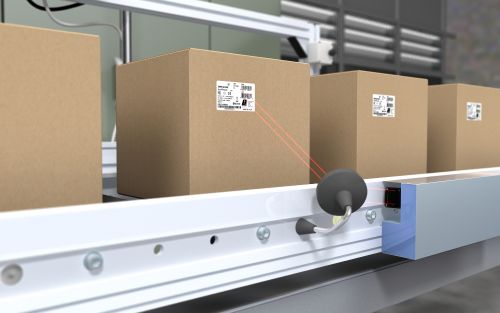
Image capture can be triggered with a binary device (like a photoelectric sensor) connected to the trigger input, a command from the process interface (EtherNet/IP or TCP/IP) or continuous capture with a fixed frame rate. The wiring schematic below shows triggering with a sensor.
- O2I5xx device
- PC for parameter setting
- Industrial PC or PLC for evaluation and triggering
- Binary sensor
- Power supply
- Optional supplemental light source
For easy connection of trigger sensors and external light sources, ifm offers Y-splitters to provide power and internal connections to further simplify wiring. Please see EVC847 (for trigger sensors) and EVC848 (for external illumination).
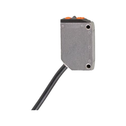
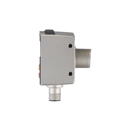
Common trigger sensors
Triggers are used to confirm that the code is in place and initiate the image evaluation process. Any sensor can be used as a trigger so long as it physically fits in the application and provides repeatable indication of the code location. Below is our most common products. Triggering can also be done with a command from a PLC.
| Part number | Description |
|---|---|
 O6P301 |
Polarized retroreflective photoelectric sensor, 5 m range |
 O6T301 |
Diffuse photoelectric sensor, 0.5 m range |
O6H301 |
Diffuse background suppression photoelectric sensor, 0.2 m range |
 OGD592 |
Precision diffuse background suppression photoelectric sensor, 0.3 m range |
 OGD580 |
Diffuse background suppression photoelectric sensor, 1.5 m range |
| Y-splitter for connection of trigger sensors |

Supplemental lighting
While the integrated LED light source in the O2I code reader provides enough illumination for most applications, there are times when additional external light is required.
| Type | Visible red | Infrared | Illuminated field | Description |
|---|---|---|---|---|
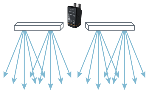 Bar Bar |
O2D921 | O2D922 | 10 x 75 mm | Highly diffuse and virtually shadow-free illumination of target |
| O2D924 | O2D925 | 10 x 150 mm | ||
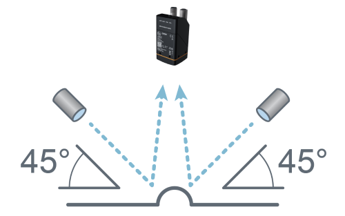 Dark field Dark field |
O2D920 | - | Ø 90 mm | Accentuate surface characteristics such as dot-peened codes |
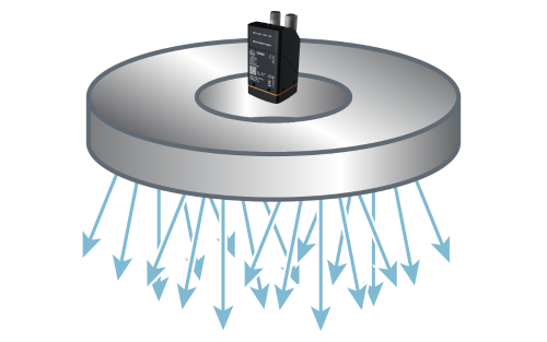 Ring Ring |
O2D915 | O2D917 |
Ø 106 mm ext Ø 66 mm int |
Homogeneous and virtually shadow-free illumination of target |
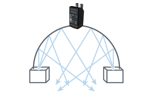 Dome Dome |
O2D931 | O2D930 | 80 x 80 mm |
Multi-angle illumination eliminates hot spots and improves reading of difficult target shapes -- AKA "cloudy day" light |
| O2D933 | O2D932 | 130 x 130 mm | ||
 EVC848 |
Y-splitter for connection of external illumination | |||