- MVQ smart valve sensors
- Setup and support
- Device configuration
Device configuration
The following information will help you quickly program the MVQ smart valve sensor. For more details, please refer to the operating instructions with the product datasheet.
Display and indications
| LED | Color MVQ101 | Color MVQ201 | Function |
|---|---|---|---|
| 1 | Yellow | White | Output 1 switching status, valve open |
| 2 | Green | Green | Voltage applied to the sensor |
| 3 | N/A | N/A | Not used |
| 4 | White | Yellow | Output 2 switching status, valve closed |
| 5 (ring) | Yellow (programmable) | Yellow (programmable) | Output 1 switching status |
| Blue (programmable) | Blue (programmable) | Output 2 switching status | |
| Red flashing | Red flashing | Fault in unit
|
|
| Green flashing | Identification mode active |
The common methods of programming the MVQ are the moneo | configure software and the moneo | blue mobile app. In addition, there are part number specific programming methods as seen below.
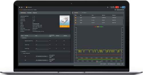
Configuration with moneo (all MVQ sensors)
moneo | configure is a user-friendly software package that enables easy programming and visualization of all ifm IO-Link enabled sensors (V1.0 and V1.1) as well as other manufacturers' IO-Link enabled sensors (V1.1). The software can be downloaded here: moneo | configure.
moneo | blue is an app that runs on your Apple or Android smart phones and provides access to all parameters, process values and diagnostics from all sensors connected to an IO-Link master. The Bluetooth™ adapter, EIO330, connects to one port of the IO-Link master and the app can be downloaded free of charge from the Apple App Store or from Google play.

Configuration with inductive teach (all MVQ sensors)
The top of the MVQ is equipped with an inductive sensor and open / closed valve positions can be taught using a metal object such as a screwdriver.
Valve open position
- Cycle the valve to the open position and move the metal object to the top of the sensor.
- Hold in this position until the LED ring flashes yellow.
- Remove the metal object. The LED ring turns to solid yellow indicating the valve is open.
Valve closed position
- Cycle the valve to the closed position and move the metal object to the top of the sensor.
- Hold in this position until the LED ring flashes blue.
- Remove the metal object. The LED ring turns to solid blue indicating the valve is closed.
Lock to avoid tampering
- Move the metal object to the top of the sensor and hold there for approx. 20 s.
- The LED ring will flash once. Remove the metal object.
- The device is locked and no changes can be made until the sensor is unlocked.
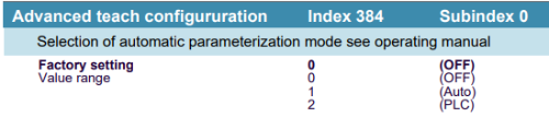
Advanced teach methods (MVQ201 only)
Because the MVQ201 has integrated solenoid control, additional programming functions are available -- Auto-teach and PLC teach -- selected via system command.
Auto-teach
The sensor triggers the solenoid control valve outputs by approaching both end positions 3 times. The open and closed positions are memorized by the sensor.
PLC teach
The sensor passively waits for the command from the PLC to move the valve to the end positions. The open and closed positions are recognized and stored by the sensor.