- MVQ smart valve sensors
- Setup and support
- Installation guidelines
Installation guidelines
The following information will help you quickly install the MVQ smart valve sensor. For more details, please refer to the operating instructions with the product datasheet.
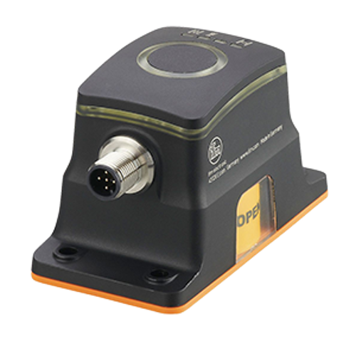
Mechanical installation (all MVQs)
Downtime is expensive. With the MVQ sensor, ifm provides the simplest mounting concept in the industry.
- Attach supplied puck to valve stem with the supplied screw.
- Place MVQ on top of the puck and attach to actuator with 4 supplied screws.
- Connect power and I/O with one standard 5-pin M12 cordset.
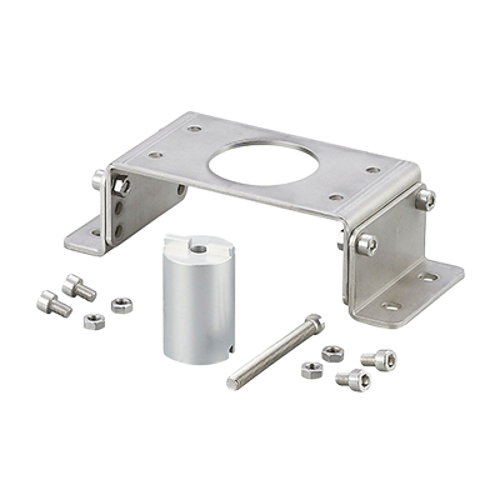
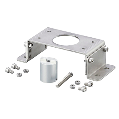
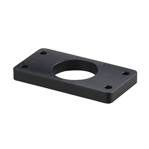
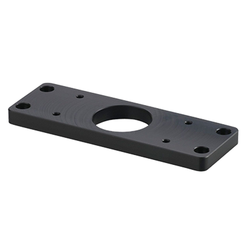
Mounting accessories
The MVQ smart sensors are designed according to NAMUR standard. Mounting interface between sensor and actuator shaft is regulated by VDI/VDE 3845 standard. Mounting accessories for different actuators are available. Refer to the actuator dimensions to determine any required mounting accessories.
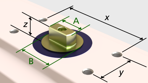
A = Shaft diameter; B = Base diameter; x, y = Hole spacing; z = Shaft height
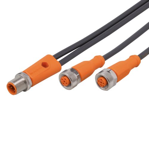
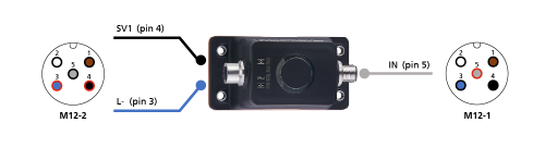
Controlling single-acting / monostable solenoid valves
- Connect a standard 5-wire M12 cordset or patchcord to your control system or IO-Link master. Pin-5 (grey wire) acts as an input to the MVQ201 sensor (M12-1 in the image).
- Connect a standard 4-wire or 5-wire patchcord directly to to your solenoid valve. The MVQ201 sensor passes the signal through the second M12 connector (M12-2).
- Internally, pin-4 (black wire) is connected to L+ of the solenoid and pin-3 (blue wire) is connected to L- of the solenoid. Pins 1, 2 and 5 are not used on M12-2.
| IN | SV1 | Result |
|---|---|---|
| Low (0) | Low (0) | Solenoid OFF |
| High (1) | High (1) | Solenoid ON |
Note: When using IO-Link, IN is automatically disabled and SV1 can be fired directly. Refer to the IODD for variable mapping.
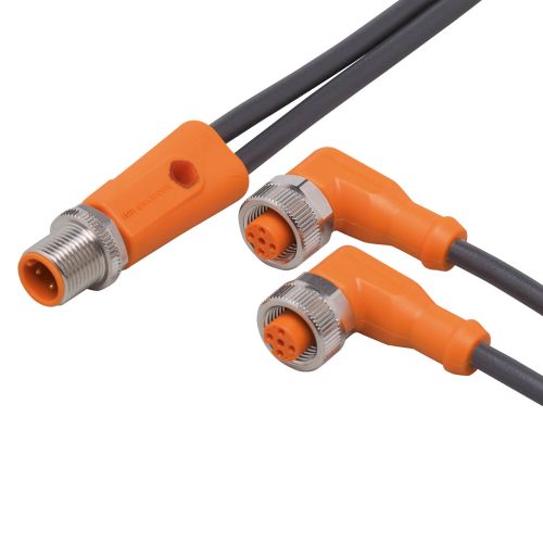
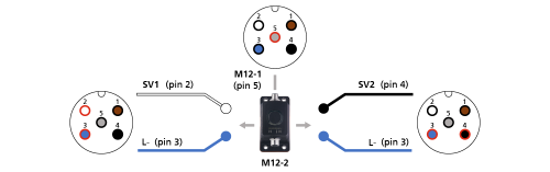
Controlling double-acting / bistable solenoid valves
- Connect a standard 5-wire M12 cordset or patchcord to your control system or IO-Link master. Pin-5 (grey wire) acts as an input to the MVQ201 sensor (M12-1 in the image).
- Connect a Y/T-splitter to each solenoid valve (SV1 and SV2). The MVQ201 sensor passes the signal through the second M12 connector (M12-2).
- Internally, pin-2 (white wire) is connected to L+ of SV1 and pin-3 (blue wire) is connected to L- of SV1.
- Internally, pin-4 (black wire) is connected to L+ of SV2 and pin-3 (blue wire) is connected to L- of SV2.
| IN | SV1 | SV2 | Result |
|---|---|---|---|
| Low (0) | High (1) | Low (0) | Solenoid 1 ON |
| High (1) | Low (0) | High (1) | Solenoid 2 ON |
Note: When using IO-Link, IN is automatically disabled and SV1 and SV2 can be fired directly. Refer to the IODD for variable mapping.