Robust connection technology
Customers in industrial automation, manufacturing, and mobile machines face tough challenges daily. Extreme temperatures, constant vibrations, exposure to oils and coolants, and demanding installation requirements can quickly degrade standard connectors, leading to signal failures, downtime, and costly maintenance.
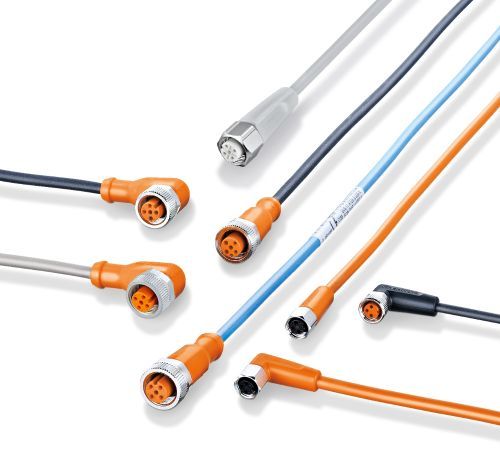
That’s why ifm developed ecolink—a connection technology built from the ground up to withstand demanding conditions for industrial automation and ensure consistent, fail-safe performance in the field.
Engineered for real-world challenges
Ratcheting coupling nut: Robust connections in high-vibration environments
In high-vibration industrial environments, loose connections can lead to sensor failures, unplanned downtime, and costly troubleshooting. The ecolink ratcheting coupling nut was designed to eliminate this risk.
ifm's sawtooth connector design actively prevents unplanned loosening of the coupling nut, keeping the connection tight and stable in environments facing heavy vibration, impact, or shock loads.
No special tools are required to install or remove ecolink connectors. The intuitive design allows for quick, secure fastening by hand - reducing installation time while ensuring a robust connection.
Mechanical end stop: Protection from overtightening, no tools required
Connector failures often result from over-tightening during installation. Excessive torque can deform O-ring seals, leading to compromised sealing, fluid ingress, and eventual connection failure. The ecolink mechanical end-stop addresses this risk by preventing over-tightening and ensuring optimal O-ring compression. This design preserves the O-ring's integrity, maintaining a perfect seal over time, even under thermal expansion, pressure changes, and repeated disconnections.
Overmolded connectors: Ingress resistance for long-term signal longevity
Industrial environments are tough on connectors - challenged with exposure to moisture, chemicals, and mechanical stress. ecolink overmolded connectors are designed and tested to withstand these harsh conditions, ensuring long-lasting performance and secure connections in demanding applications.
ecolink's overmolded design creates a watertight, dustproof barrier on each connector, preventing contaminants from compromising electrical connections.
Unlike standard connectors, overmolding also eliminates weak points where cables meet connectors - reducing cable fatigue, preventing breakage, and extending product lifespan while ensuring signal integrity in demanding applications.