- PI sanitary pressure transmitter
- Setup and support
- Device configuration
Configuring the PI pressure transmitters
Configuration and parameterization via software or display
Parameter setting of the PI1 can be carried out via the IO-Link interface or via the push button elements on the unit. More details can be found below on this page or in the operating instructions on the the product datasheet page under the Downloads tab.
You can also visit our installation instructions or FAQs page. Should you need additional support with your pressure transmitter, feel free to contact our service center at 800-441-8246 and speak to one of our Application Engineers.

moneo | configure
moneo | configure is a user-friendly software package that enables easy programming and visualization of all ifm IO-Link enabled sensors (V1,0 and V1.1) as well as other manufacturers' IO-Link enabled sensors (V1.1). The software can be downloaded here: moneo | configure.

moneo | blue
moneo | blue is an app that runs on your Apple or Android smart phones and provides access to all parameters, process values and diagnostics from all sensors connected to an IO-Link master. The Bluetooth adapter EI0330, connects to one port of the IO-Link master and the app can be downloaded free of charge from the Apple App Store or from Google Play.
Onboard pushbuttons
The sensor can be set without any additional tools or software using the integrated display and pushbuttons. This is a convenient option to interact with the device in the field or when a PC is not available or IO-Link and Bluetooth are not installed.
Programming video using pushbuttons
Display indications and programming features
The PI pressure transmitter displays system pressure. Indications:
- LEDs 1...6 indicate selected units of measure for pressure process values
- LED 7 indicates switching status of OUT2 (on if output 2 is switched)
- LED 8 indicates switching status of OUT1 (on if output 1 is switched)
- 9: Enter [E] button to enter the programming menu and confirm the parameter setting value
- 10 and 11: Arrow keys up [U] and down [D]
- 12: 4-digit alphanumeric display for indication of process values, parameters and parameter values
Common programming features
All of ifm's process sensors, including the PI series pressure transmitters, use similar terminology for programming. We highlight the features used most often here. Refer to the Operating Instructions manual found under the "Downloads" tab at the product datasheet page for more details on these and other features.
Calibration and verification
ifm's PI pressure sensor is an all-in-one transmitter and does not require calibration in the field prior to use.
Factory calibration
Each pressure sensor is factory calibrated during production to offer excellent performance out of the box.
- During production the sensor electronics go through 5-point calibration (0, 25, 50, 75, 100% of measuring range)
- Calibration is verified by testing 100% of the devices at the end of production. Information from the calibration verification during production can be found in the Factory Certificate provided by ifm.
- Download a free factory certificate from our website. Be sure to have the serial number of the sensor to enter.
- The certificate also includes accuracy of the digital (IO-Link) measurement.
Field calibration
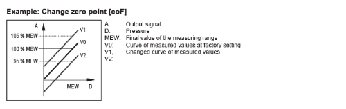
ifm pressure sensors come ready to use out of the box but can also be adjusted in the field to match a known value or calibrated reference device. The two main parameters that can be adjusted are the Zero Point Calibration [coF] and Calibration Gain [CGA]. The customer specific calibration changes the curve of the measured values in the sensor compared to the real process value.
Zero Point Calibration [coF] and [tcoF] adjusts the complete measurement up or down in a linear fashion by the percentage entered. This function can be used to adjust for a constant offset in the sensor that can be seen when there is zero pressure applied. The internal zero reference is shifted by this value.
- [tcoF] can be used to automatically teach the zero-point calibration. Make sure there is no pressure applied to the system.
- The zero calibration can be manually adjusted from -5%...+5% of the final value of the measuring range and it is calculated by subtracting the known value (P1) from the measured value (P2) and dividing that by the final value of the measuring range (VMR).
[coF] = (P2 - P1) ÷ VMR x 100
Calibration gain [CGA] adjusts the measurement curve gradient of the sensor to match the pressure of a known value or reference sensor.
The gain can be adjusted from -5%...+5% of the final value of the measuring range and it is calculated by dividing the known value (P1) by the measured value (P2).
[CGA] = (P1 / P2 – 1) x 100

Note: If [coF] and [CGA] are changed the analog output will change accordingly.