- LW radar level sensor
- Setup and support
- Device configuration
LW radar level sensor: Device configuration
The following guides you through key programming steps for the LW level sensors. More details can be found in the operating instructions on the product datasheet page under the Downloads tab.
Quick start setup

Setup with moneo | configure
moneo | configure is a user-friendly software package that enables easy programming and visualization of all ifm IO-Link enabled sensors (V1.0 and V1.1) as well as other manufacturers' IO-Link enabled sensors (V1.1). The software can be downloaded here: moneo | configure.
Setup with moneo | blue app
moneo | blue is an app that runs on your Apple or Android smart phones and provides access to all parameters, process values and diagnostics from all sensors connected to an IO-Link master. The Bluetooth™ adapter, EIO330, connects to one port of the IO-Link master and the app can be downloaded free of charge from the Apple App Store or from Google play.

Commissioning support with ifm Vision Assistant
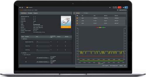
Vision Assistant is a software that provides support during commissioning. The LW radar sensor can be visualized and parameterized within Vision Assistant. Parameters such as the Reference distance, Bottom offset, and Upper null zone can be set directly in the software. The set parameters are written directly to the sensor and the software provides real-time feedback of the echoes and echo strength of the signals its evaluating.
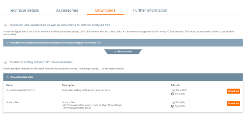
Where to find the Vision Assistant software
The Vision Assistant can be found directly on the LW2120 and LW2720 product page under "Downloads".
The following explains the key adjustable parameters that are most often used in typical applications. Refer to the operating instructions for details on all available parameters.
Reference height -- distance between the sensor and the zero point. The zero point may not necessarily be the bottom of the tank.
- Setting range = 0.2...15 m
- Reference height does not have a factory default value. Reference height might be entered before device is operational.
A = lower / sealing edge of process connection
B = Reference height / measuring range
C = zero point / lower end of measuring range
Tank offset -- Distance between the zero point and the actual tank bottom.
- Setting range = -10...10 m
A = lower / sealing edge of process connection
B = Reference height / measuring range
C = zero point / lower end of measuring range
D = tank offset value
Upper blind zone -- Distance immediately below the sensor where echoes are ignored.This suppresses false echoes from mounting, spray balls or other obstructions.
- Setting range = 0...10 m
A = upper blind zone
B = false echo
C = 100% / 20 mA of the analog signal, below the upper blind zone but within the reference height
D = detection threshold
E = medium surface echo
Detection threshold -- The detection threshold filters out noise and disturbing echoes from the medium surface echo. For most applications, adjustment is not required. The signal strength must be greater than the detection threshold to be recognized as "level".
- Setting range = 0...20,000 mV
Increase if echoes are received from obstructions.
Decrease if echoes from surface are weak due to foam or low dielectric media.
D = detection threshold
E = medium surface echo
Configuration examples -- positive bottom offset and negative bottom offset
Applications with obstructions or other interferences at the tank bottom
- Upper blind zone = 0.25 m
- Reference height = 2.5 m
- Analog signal range
- ASP2 = 0 m; Analog start point represents 4 mA, typically the zero point of the tank
- AEP2 < 2.25 m; Analog end point represents 20 mA, recomended maximum is reference height minus upper blind zone
- Zero point
- Bottom offset = 0.5 m
Positive bottom offset is used in situations where the you want to ignore the lower part of the tank (Reference height < tank height) and have the zero point above the actual bottom of the tank. The sensor therefore does not measure below the offset and ignores obstructions like agitators, mixers, or other obstructions in the tank. This helps the sensor block out unwanted or erroneous signals that could otherwise create interference.
Applications with measurements in bypasses
- Reference height = 10 m
- Analog signal range
- ASP2 = 0 m; Analog start point represents 4 mA, typically the zero point of the tank
- AEP2 ≤ 10 m; Analog end point represents 20 mA, maximum is reference height minus upper blind zone
- Zero point
- Bottom offset = - 2.5 m
- Alarm delay = 50 s
Negative bottom offset is used in situations where the overall level to be measured is greater than the tank height (Reference height > tank height) and you want the sensor to show level even when the measured tank is empty. This parameter set can be used in bypass situations for example. In this example the level will measure 2.5 m when the bypass is empty and then alarm in 50 s if the bypass remains empty. This helps provide a more accurate representation of the level when measuring in a reference tank or location that does not have a view to the true bottom of the tank.