- LW radar level sensor
- Setup and support
LW Radar level sensor: Installation guidelines
For the best performance of the LW family of sensors, please adhere to the guidelines on this page and in the operating instructions posted with the product datasheet.
Should you need additional support, feel free to contact our service center at 888-704-0702 and speak to one of our applications engineers.
Note: Only install in closed metallic tanks
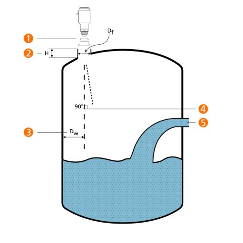
Mounting in tanks with dished heads
Dished heads can act like parabolic antennas:
There is a risk of multiple echoes if the geometry is unfavourable. When the tank is empty false echoes below the zero point are cut off and may go unnoticed, so test with media in the tank to see if false echoes below the surface exist.
Corrective measure:
Mount the sensor off-center. Recommended mounting position is ½ tank radius or closer to the sidewall.
Ferrule diameter vs. ferrule height
| Diameter (Df) | Height (H) |
|---|---|
| 1.5 " (40 mm) | 5.9" (150 mm) |
| 2" (50 mm) | 7.9" (200 mm) |
| 3" (80 mm) | 11.8" (300 mm) |
| 4" (100 mm) | 15.8" (400 mm) |
| 6" (150 mm) | 23.6" (600 mm |
Note: For installation in accordance to 3A requirements, the ferrule height must not exceed 5" (127 mm) or 2x the diameter.
Beam profile
As discussed on the Technology page, the higher the frequency of the radar device, the smaller the beam angle. Operating at 80 GHz, the LW sensor has a 10º angle (α).
Beam width (W) vs. Distance (D)
| Distance (D) | Beam width (W) |
|---|---|
| 6.6' (2 m) | 1.2' (0.4 m) |
| 13.1' (4 m) | 2.3' (0.7 m) |
| 19.7' (6 m) | 3.5' (1.1 m) |
| 26.2' (8 m) | 4.6' (1.4 m) |
| 32.8' (10 m) | 5.8' (1.8 m) |
Orientation of sensor relative to the tank wall
Mount the sensor such that the M12 electrical connection is at a 45º angle from the tank wall since the radiation cone is ovular. This orientation will reduce interference from the tank wall and provide optimal signal strength.
Temperature limitations
The combination of the temperatures from both the ambient environment and the media should be taken into consideration to maintain he life of the sensor. As with most sensors, the main limitation is the temperature rating of the electronics, which can be heavily influenced by the ambient environment. In applications with hot media, ambient cooling helps to keep the electronics within their working limits. Please use this diagram to determine if the continuous temperatures in your application are allowable.
x-axis = Medium temperature (ºC)
y-axis = Ambient temperature (ºC)
Ex. 1: For medium temperature of 150 ºC, maximum ambient temperature is 40 ºC.
Ex. 2: For ambient temperature of 80 ºC, maximum medium temperature is 80 ºC.
Mounting with adapters
A sealing gasket comes with the sensor. This gasket prevents contaminants from the outside from getting inside the process. Another sealing o-ring comes with the adapter and this o-ring provides the seal required for 3A authorization. Follow the instructions as shown.
- Place the o-ring in the groove at the base of the sensor. Take care to keep the antenna surface scratch-free.
- Lightly grease the sensor threads with appropriate lubricating paste (not supplied by ifm). Ensure the paste is suitable for the application and chemically compatible.
- Ensure the o-ring is mounted in the groove of the sensor and screw into the adapter. Recommended tightening torque is 35 Nm.
Special instructions for weld fittings
- Use weld mandrel to prevent warpage during welding.
- Use arrow to align the position of the M12 electrical connector.
- When cleaning up welds, make sure not to damage the sealing edge of the sensor. This will cause leaks.
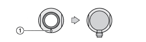
Align the mark on the fitting (1) with the final orientation of the M12 electrical connector