HF (High-Frequency) RFID systems: HF Technology
A high frequency RFID system consists of a reader/antenna and a tag. It operates using inductive coupling. The antenna creates an inductive field surrounding the tag, which creates a current on the tag itself. The current charges the chip with enough power to both read / write the onboard memory and manipulate the inductive field to allow for wireless communication.
Communication is between a single antenna and a single tag at any given time.
- Improves reliability (no interference)
- Antenna can trigger read/write cycles itself
- PLC or higher-level control can trigger read / write cycles
- The tag must be within the inductive field.
- RF absorbing materials such as water, water-based chemicals and metals, can affect the inductive field.
- Specialized pre-tuned tags are required for applications where RF absorbing materials are present.
The two common standards for HF RFID are ISO 14443 (Near Field Communication technology or “proximity”) and ISO 15693 (Industrial RFID technology or “vicinity”). ifm’s 13.56 MHz systems are based on the ISO 15693 standard.
| ISO 15693 Vicinity | ISO 14443 Proximity | |
|---|---|---|
| Data transfer rate | Slower | Faster |
| Read/write distance | Larger | Shorter |
| Durability | Greater | Lesser |
| Common applications | Error proofing Production control |
Building access High data transfer |
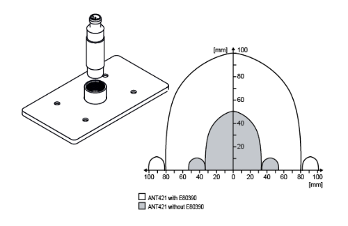
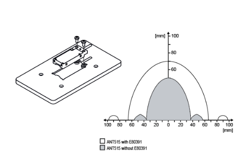
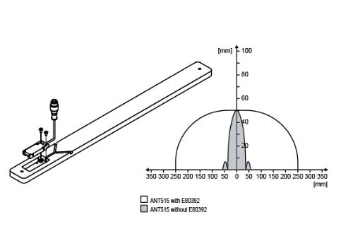
Amplifier plates are passive devices that contain circuitry and antenna coils tuned to amplify the signal of an installed antenna. They either increase the read distance or increase the dwell time, depending on the version. For optimal performance, install amplifier plates at least 100 mm from any metal.
E80390 – use with M18 diameter antennas. It approximately doubles the read distance.
E80391 - use with the flat rectangular antennas. It increases read distance by approximately 40%.
E80392 – use with the flat rectangular antennas. It increases the dwell time by approximately 5 times.
Tags, or transponders, house the desired data in memory and send that data via radio waves when energized by the antenna. Tags come in different geometries and with different properties. Refer to installation guidelines for assistance in non-standard applications.
| Tag type | Properties |
|---|---|
| Standard tags | Maximum read / write distance for standard applications. |
| Pre-tuned tags | Tuned to a preinstalled metal film backing to allow mounting on metal. Performance is usually similar when not installed on metal. Some specially tuned to increase read / write distance on metal. |
| Metal-embeddable tags | Specially tuned to be flush mounted in metal. Usually a friction fit into a drilled hole in the carrier. |
| High temperature tags |
Built with additional shielding to withstand temperature up to 450 °C. |
| Labels | Low cost solution for tracking of materials and components. Consists of adhesive backing with a thin printed RFID inlay antenna and chipset. Labels can be mounted directly on metal or onto standard targets. |
| Databolts, cards, bracelets and fobs | Specialized tags for targeted applications. Databolts are metal hex bolts for easy mounting into a tapped hole. Cards, bracelets and fobs are specially tuned for close proximity to the human body and are typically used for access control. |
Tag reading and writing
HF RFID communication relies on the tag’s ability to effectively manipulate the inductive field produced by the antenna. Read / write distance is based on the relationship between the tag and antenna, not either one alone. Generally, the larger the tag, the longer read distance with a given antenna. Read / write distances of 230 mm can be achieved with certain antenna / tag combinations.
Speed of data transfer is influenced by two main factors.
- RFID system itself – modular systems are best for high speed applications (< 500 msec for 2 kbytes) while IO-Link systems are best for low speed or static applications (> 500 ms for 2 kbytes).
- Amount of data – reading / writing individual blocks significantly reduces cycle time.
Other factors to consider are optimization of block sizes and the memory type.
Memory
The following tables compare the various memory available for RFID tags.
| UID (Unique Identifier) | User Memory |
|---|---|
| Locked unique identifier - 8 bytes | Memory for manipulation |
| Cannot be changed | Storage for process information or UID number |
| 112...64k bytes |
| EEPROM | FRAM |
|---|---|
| 100,000 read/write cycles | 1 trillion read/write cycles |
| Write process followed by read confirmation | 1000 times faster than EEPROM |
| Slightly larger read/write distance | Single process for read/write |
| Slightly shorter read/write distance |
Block sizes
The block size is the smallest memory size that can be written in one cycle.
- As tag memory increases, block size increases.
- Each block is individually addressed, so the blocks can be written independently, maximizing write cycle speed.
- Maximum number of blocks per tag is 256 and common block sizes are 4, 8 and 32 bytes.
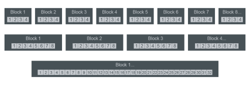
Common byte size per block - click on magnifying glass to enlarge
Why is block size important?
- Matching communication types – a single read / write head is programmed to read a specific block size within an application. Readability issues occur if the block size is different from what is expected.
- Optimizing write speeds – a full memory address must be written. By selecting a block size that matches the amount of data you have, you avoid the added time to write unused capacity.