- Discover TCC
- Setup and support
- Installation guidelines
Installation guidelines
For the best performance of the TCC family of sensors, please adhere to the guidelines on this page.
Should you need additional support, feel free to contact our service center at 888-704-0702 and speak to one of our applications engineers.
There are four basic variants for the TCC family as shown in the table below.
| Description | Process connectors | |
|---|---|---|
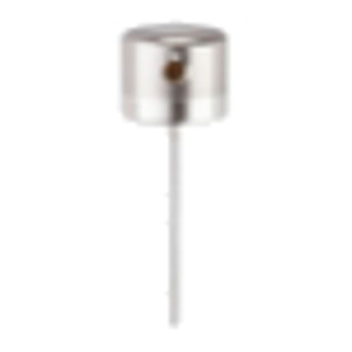 TCC2xx TCC2xx |
Ø6 mm stick probe, 100…550 mm insertion length | Required. Use E30144 compression fitting and one of the process connectors below. |
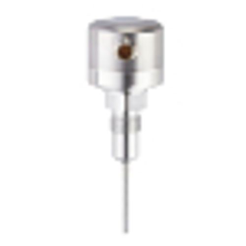 TCC5xx TCC5xx |
Ø6 mm probe, 30…1000 mm insertion length, G ½” sanitary sealing cone | Required. Use E43911 PEEK sealing ring and either a clamp fitting or welding fitting. |
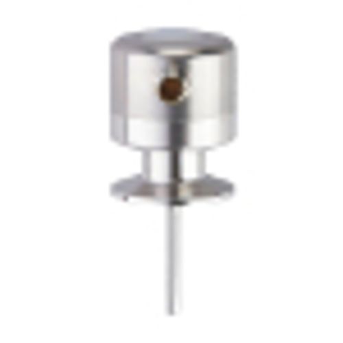 TCC8xx TCC8xx |
Ø6 mm probe, 50…100 mm insertion length, integrated 1.5” triclamp | N/A - 1.5” triclamp connection is integrated. |
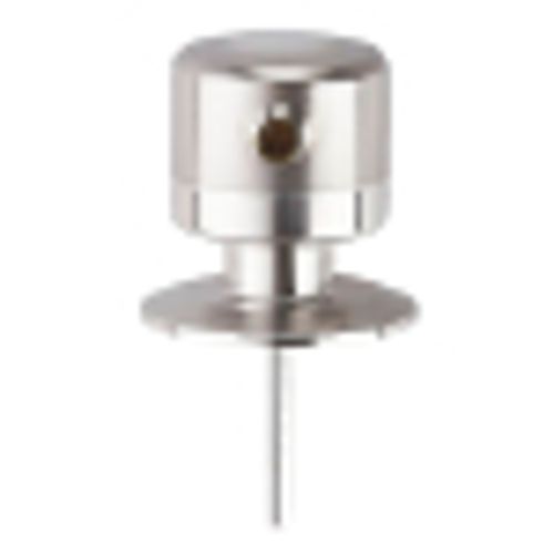 TCC9xx TCC9xx |
Ø6 mm probe, 50…100 mm insertion length, integrated 2” triclamp | N/A - 2” triclamp connection is integrated. |
Sensor orientation
For best cleanability, do not install the sensor at the lowest point of the pipe or tank as shown by position 5 in the image. This allows the medium to run off the probe and avoid building up over time.
Leakage ports, or weep holes, in process fittings, are required for installations in accordance with 3A guidelines. When an o-ring is place, the process medium remains in the tank or pipe. If that o-ring is compromised, i.e. missing or damaged, the medium will leak at the weep hole. This is an indication that the o-ring must be replaced.

Typical orientation of a leakage port
Be sure to install the fitting such that the weep hole points downward.