- Discover TCC
- Reinventing the calibration process
Reinventing the calibration process
What if you could eliminate product quality risk due to inaccurate process temperature measurement between calibration cycles?
ifm’s “Calibration Check” technology provides real-time continuous monitoring of instrument accuracy and measurement uncertainty. A large, bright LED dome provides an immediate signal of any deviation from the user-specified tolerance.

What if your temperature instrument could reduce your total cost of ownership?
Initial purchase price of an instrument is generally only a small percentage of the total cost of ownership equation.

ifm’s “Calibration Check” technology automates manual periodic calibration checks. By eliminating mistakes from manual measurements and hand-recorded values, you ensure accurate time-stamped quality records.
Typical periodic calibration verification cycle
- Install: It is necessary to install two identical units next to each other. Typically, both units are affected by drift in the same way.
- Remove: Periodically, remove a unit from service. Frequency depends on each user’s quality process.
- Check: Check the calibration of the unit against a known standard. This is done in-house by the user or by third party labs.
- Validate manually: Validate the results.
- Document manually: Document the results.
- Reinstall: Reinstall the unit.
Automated continuous calibration verification with IO-Link
- Install: A single TCC takes the place of two standard transmitters.
- Measurement: Measured process value sent to PLC via IO-Link for process control.
- Document automatically: Via IoT port, record time-stamped PT and NTC measured values.
- Check automatically: Automatically check documented values for drift.
- Continue: This verification cycle continues without the need to remove the TCC from service.
At-a-glance indication of sensor health
In addition to automating the calibration process, the "Calibration check technology" of the TCC provides real-time monitoring of instrument accuracy. The TCC signals deviation from a user-specified tolerance electronically as well as visually when the LED changes color.
- Monitors measurement uncertainty 24/7 between calibration intervals.
- Minimizes product loss / quality impact as a result of inaccurate measurement between calibration intervals.
- Eliminates errors caused by manual measurement or manual data storage with automatic data logging.
- Potentially reduces the number of formal calibration verification checks.
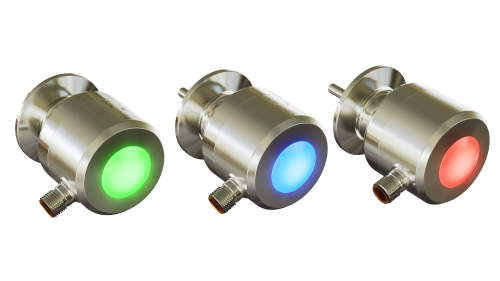
LED color provides immediate visual feedback of sensor health
Green -- Normal operation. Monitors calibration check and on-board diagnostics.
| Temperature (PT) | Reference temperature (NTC) | Calibration check status (OUT1) | Analog signal (OUT2) | |
|---|---|---|---|---|
| Calibration check |  |
|
On | |
| On-board diagnostics | |
|
On | |
Blue -- Alert mode. Signals a warning.
- Specified calibration check limit exceeded
- Reference element (NTC) defective
- Calibration check function not available
| Temperature (PT) | Reference temperature (NTC) * | Calibration check status (OUT1) | Analog signal (OUT2) | |
|---|---|---|---|---|
| Calibration check | |
|
Off | |
* In case of a defective reference element, the NTC temperature value will not be provided.
Red -- Error mode. On-board diagnostics error signaled.
| Temperature (PT) | Reference temperature (NTC) | Calibration check status (OUT1) | Analog signal (OUT2) | |
|---|---|---|---|---|
| Calibration check |  |
** | Off | 21.5 mA or 3.5 mA |
** The NTC temperature value is provided but only over IO-Link.