- TW infrared temperature transmitters
- Setup and support
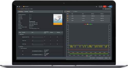
- Device configuration
Parameterization via software or display
The following guides you through key programming steps for the TW infrared temperature transmitter. More details can be found in the operating instructions on the the product datasheet page under the Downloads tab.
moneo | configure is a user-friendly software package that enables easy programming and visualization of all ifm IO-Link enabled sensors (V1.0 and V1.1) as well as other manufacturers' IO-Link enabled sensors (V1.1). The software can be downloaded here: moneo | configure.
moneo | blue is an app that runs on your Apple or Android smart phones and provides access to all parameters, process values and diagnostics from all sensors connected to an IO-Link master. The Bluetooth™ adapter, EIO330, connects to one port of the IO-Link master and the app can be downloaded free of charge from the Apple App Store or from Google play.

General use of pushbuttons
Programming of the infrared temperature transmitter has been made easy with the LED display and 3-button programming.
| 1 | Press [Enter] once to enter programming mode. |
|---|---|
| 2 | Press Up or Down arrow [▲/▼] to view parameters or additional menus. |
| 3 | To change setting, press [Enter] and then Up or Down arrow [▲/▼] and hold until the display begins to flash. Then press Up or Down arrow [▲/▼] to toggle through options. |
| 4 | When desired value is reached, press [Enter] to confirm the setting. |
(Note: Holding the up/down buttons pressed will scroll through parameters; while pressing once will incrementally go through parameters.)
Required configuration for set-up
When the supply voltage is switched on for the first time or after reset of the parameters to factory setting, dashed lines are on the display. This means the emissivity has to be set.
Set the emissivity [EPSI]
| 1 | Press [Enter]. [EPSI] is indicated in the display. |
|---|---|
| 2 | Press [Enter]. [nonE] is indicated in the display. |
| 3 | Press and hold [▼] until the requested value is indicated. |
| 4 | Press [Enter]. The current temperature value is displayed. |
Note: An incorrectly set emissivity leads to faults during temperature measurement. The emissivities indicated in the tables of the operating manual are approximate values. To determine the temperature precisely a reference value measurement should be made. To compensate environmental influences it may be useful to set a higher emissivity.
TW2000 / TW2003 / TW2100 emissivity set-up with supplied label
The emissivity setting of the specified TW's can be set using the supplied label for temperatures up to a maximum of 250 °C.
| 1 | Select [EPSI] and set the emissivity to 94%. |
|---|---|
| 2 | Apply the label to the object to be measured and measure the temperature with the infrared temperature sensor (reference temperature). |
| 3 | Remove the label and measure the temperature of the object again. The displayed temperature deviates from the reference temperature. |
| 4 | Select [EPSI] and change the emissivity. |
| 5 | Measure the object again. |
| 6 | Repeat the process until the displayed value corresponds to the determined reference temperature. |
Note: Ensure during the measurements that the temperature of the object to be measured remains constant. Decreasing the emissivity leads to an increased temperature display and vice versa.
Common programming features
All of ifm's process sensors, including the TW infrared temperature transmitters, use similar terminology for programming. We highlight the features used most often here. Refer to the Operating Instructions manual found under the "Downloads" tab at the product datasheet page for more details on these and other features.
Switching outputs
-
Hno -- hysteresis normally open: Output turns on when the set point (SP) is reached and stays on until the temperature drops below the reset point (rP)
-
Hnc -- hysteresis normally closed: Output turns off when the set point (SP) is reached and stays off until the temperature drops below the reset point (rP)
Analog outputs
-
ASP -- analog start point: The temperature where the analog signal equals 4 mA.
-
AEP -- analog end point: The temperature where the analog signal equals 20 mA.
-
MAW -- initial value of the non-scaled measuring range.
-
MEW -- final value of the non-scaled measuring range.
The minimum scaled measuring range is available on the product datasheet.
Additional configurations and functions for special circumstances
Damping function - stabilizes the measured signal if there are brief fluctations in the temperature of the object being measured. The higher the selected time constant [dAP] the lower the influence of the interfering temperature fluctuations on the measured value.
Peak-hold function - maintains the highest measured temperature value for the time duration set in the peak hold [Phld] parameter. Useful in applications with moving targets or cyclically occuring temperatures. During this hold time only the maximal measured value is displayed and provided. It is recommended to set the hold time to approximately 1.5 x the object cycle time. The hold time [Phld] can be set to 0...600 s.
Simulation function - activate a simulated measured temperature within the measuring range using the SIM parameter in the menu. The simulation influences the display, digital, analog and IO-Link signals which is helpful when setting up and installing the device.
Test function - drive the analog and IO-Link signals to 20.5 mA or OL to check the complete signal processing. This internal test function can be activated by a static signal on pin 5 in which it is in the test mode until the signal is removed. Or it can be activated via IO-Link in which the duration is 10 s.