- MVQ positioner solution
- Setup and support
- Device configuration
MVQ valve positioner: Device configuration
The following information will help you quickly program the IO-Link enabled valve positioner after installing your MVQ valve sensor. For more details, please refer to the operating instructions with the product datasheet.
Configuration with moneo

moneo | configure is a user-friendly software package that enables easy programming and visualization of all ifm IO-Link enabled sensors (V1.0 and V1.1) as well as other manufacturers' IO-Link enabled sensors (V1.1). The software can be downloaded here: moneo | configure.

moneo | blue is an app that runs on your Apple or Android smart phones and provides access to all parameters, process values and diagnostics from all sensors connected to an IO-Link master. The Bluetooth™ adapter, EIO330, connects to one port of the IO-Link master and the app can be downloaded free of charge from the Apple App Store or from Google play.
Electrical connection to the solenoid and IO-Link master
Configurating the MVQ positioner
Step-by-step configuration
The MVQ positioner can be configured very quickly with just 3 steps via moneo configure.
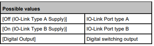
Step 1: Enable B-ports
B-type ports on an IO-Link master e.g., AL1422 are disabled by default. First connect the IO-Link master to moneo and enable the B-ports.
Step 2: Select valve rotation
Default setting: Counter clock-wise.
If your valve is counter clock-wise, you do not need to change this configuration.

Step 3: Automatic valve setup
Under the “Valve setup” section, you will find “Advanced teach configuration”. Click on the dropdown button and you will find 2 options: Automatic valve setup and positioning tuning; and Automatic valve setup.
For quick setup, click on “Automatic valve setup” and write to the device, then click on “Execute command”.
The sensor will learn the current position of the valve, and study which solenoid should be energized and move the valve from 0% (close) to 100% (open). The teach is now done.
The User can then define the desired position and input it to the sensor.

The MVQ positioner provides clear feedback via its indicators and the control system when the desired position is reached. This allows operators to easily monitor and optimise processes, resulting in increased efficiency and productivity.

LED ring
The LED ring of the MVQ positioner offers a wide range of color options, including red, green, yellow, blue, magenta, cyan and white. The LEDs can be continuously lit or flashed at different frequencies to visualize different operating states. The colors can be individually selected and adapted via IO-Link to meet your application requirements.
| Action | Indication | Color | Default color |
|---|---|---|---|
| Advanced teach | Flashes with a frequency of 1 Hz as long as the advanced teach is running. | selectable via IO-Link: [OFF], [green], [blue], [yellow], [magenta], [cyan], [white] Default: [white] | white |
| Within the deadband | Lights when the actual value is in the deadband and control is completed. | white | |
| Control active | Flashes with a frequency of 1 Hz as long as the control is active. | OFF | |
| Close | Lights when the actual value is <= SC1.2. | blue | |
| Open | Lights when the actual value is >= SC1.1. | yellow | |
| Locator | Double flashing | green | |
| Error | Flashes with a frequency of 1 Hz as long as the error is present. Minimum display time 3 seconds. | red | |
Status LEDs
| LED name | Color | Operating status |
|---|---|---|
 |
Green | Statically on when the device is ready for operation. |
 Open |
White | Statically on when the valve is open. (SC1.1 active) |
 Close |
Statically on when the valve is closed. (SC1.2 active) |
|
 In position |
Statically on when the actual valve is in the deadband and control is completed. |
Puck

The mechanical position indicator (puck) shows the valve position even when the device is not powered.
Read more about frequently-asked questions about MVQ valve positioners.