- MVQ positioner solution
- Setup and support


Figure overview:
- Hexagon socket screw 4 x M5 x 16
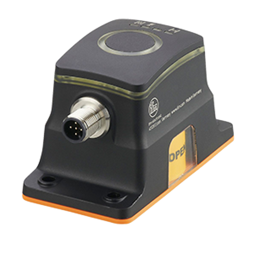
- Sensor and control unit MVQ301
- Hexagon socket screw 1 x M6 x 12
- Puck
- Throttle plate
- Solenoid valve
- Cylinder screw 2 x M5 x 45
Installation steps:
- Use the notch located at the bottom of the puck as a mounting aid for a precise positioning on the shaft. Align the puck and fasten the puck to the valve shaft using the screw supplied [3], tightening torque 1.2 Nm.
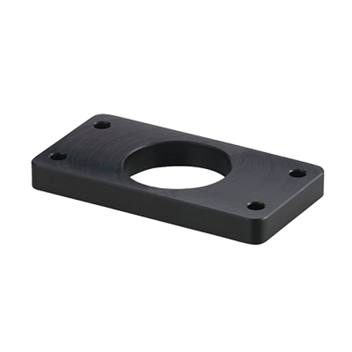
- Put the device [2] over the puck [4] and fix the sensor to the actuator housing using the supplied screws [1]. Use an optional mounting plate, depending on the mechanical interface.
- Install the throttle plate [5] and the solenoid control valve [6] with the screws supplied [7], connect the airline to the solenoid valve [6].
- When the system is complete, turn the power and compressed air on, and the positioner is ready to be configured.
Caution: Before dismantling the throttle plate or solenoid valve, ensure that no pressure is applied to all chambers of the actuator. Alternatively: Unscrew the throttle plate or solenoid valve very slowly and allow the trapped compressed air to escape.
Below are the pneumatic switching symbols of the solenoid valves that ifm supplies.


*Confirm the location of the spring chamber. Connect Port 3 on the solenoid and throttle plate to the spring chamber. If the valve fails to move during the automatic teaching process, loosen the air ports on the throttle plate to allow air to flow into the actuator. For optimal performance, set the cycle time (from closed to open) to 3 seconds.
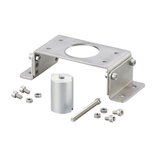
Mounting to a double acting actuator using the ZZ0688 positioner kit
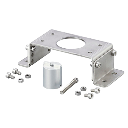
Mounting to a spring return actuator using the ZZ0687 positioner kit
The intelligent valve positioners from ifm are designed according to NAMUR standard. Mounting interface between sensor and actuator shaft is regulated by VDI/VDE 3845 standard. Mounting accessories for different actuators are available. Refer to the actuator dimensions to determine any required mounting accessories.
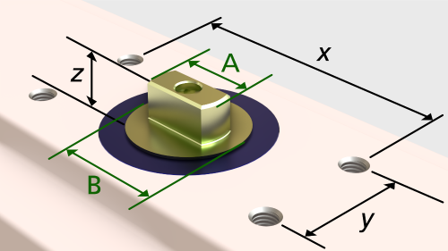
A = Shaft diameter; B = Base diameter; x, y = Hole spacing; z = Shaft height