- Inclination sensors
- Technology
Inclination sensors:Technology
MEMS technology
Most of the inclination sensors (also called inclinometers, tilt or slope sensors) available on the market today feature a multi-axis MEMS (MicroElectroMechanical System) accelerometer. These types of measuring cells are very small, precise and robust as well as wear- and maintenance-free.
The MEMS measuring cell consists of two main components -- one movable electronic part and one fixed mechanical part.
- The movable part consists of a proof (seismic) mass with electrodes on the outer edge suspended by springs.
- The fixed part consists of fixed electrodes.
- The electrodes located at minimum distance to each other form a “comb”.
When the sensor is in a horizontal position, the z-axis of the sensor is usually parallel to the earth vector. Thus, its value is “absolute” zero. If the sensor is tilted in one direction, the movable mass inside and its electrode will change position relative to the fixed electrode.

Detailed view of an MEMS cell
1) Movement (acceleration)
2) Comb electrodes with ~1.3 µm distance to each other
The resulting change of capacitance between these two electrodes is detected by the measuring cell and used to calculate the final angle value.
IMPORTANT!
Each inclination sensor is factory-supplied with absolute calibration. The reference used is the gravitational vector, i.e. the gravitational acceleration, 1g (= 9.81 m/s²). If a measurement axis of the sensor is parallel or congruent with the earth vector, no angle measurement can take place; the sensor lacks orientation in this position. As a result, a direct angle measurement (rotation detection) around the vertical reference axis (yaw angle) is not possible. However, the yaw angle can be calculated indirectly via an external PLC.
Angle definitions
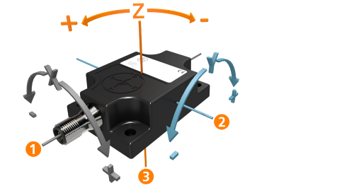
Angle definition with zero position z-axis = gravitational vector
1) y-axis “roll” (longitudinal) ⇒ angle x
2) x-axis “pitch” (lateral) ⇒ angle y
3) z-axis “yaw” (vertical)⇒ angle z
Static inclination sensors
This type of inclination sensor is mainly used in static or quasi-static applications such as scissor lifts. Such machines require high static accuracy, however, the sensor is subject to minimal vibration. In applications where diffuse, external accelerations are more frequent, software filters can be used to smooth the sensor signal.
Digital filters for such sensors are usually “moving average” filters. The downside is that while the values appear much more stable, the reaction time of the sensor is affected. In extreme cases, a trade-off between stability and response time must be found.
Static inclination sensors with 3 degrees of freedom (JN series)
Often the horizontal alignment of machines or machine parts is an important requirement for reliable operation. Inclination sensors based on the static measurement principle are designed for angular position detection or levelling of stationary mobile machinery.
They are commonly used for position detection on working platforms or leveling of mobile cranes or excavators. Industrial applications include solar panel tracking systems.
Additional functionalities of the static inclination sensor [JNxxx0]
- The integrated MEMS measuring cell makes it possible to provide all raw 3D data of the accelerometer in parallel with (via CANopen and J1939) or sequentially to the 2D inclination values (via IO-Link).
- Calculated characteristic values of the three axes, such as the vibration velocity [v-RMS] and the vibration acceleration [a-Peak] can be read out directly.
- Predefined filter levels (e.g. 0.1-10Hz) and an axis selection can be set to suit the application.
- The low-frequency detection range of the measuring cells makes it possible to detect structural vibration or tower vibration to ISO4866 or monitor machines to ISO10816.
- Typical applications are cooling and wind towers or earthquake detection systems.
Limitations of static inclination sensors
In static applications with strong shock and vibration, software filtering or damping of the measurement signal might not be sufficient. In addition, a compromise between signal stability and response time is often not possible due to the application. Moreover, accelerations of vehicles at the moment of starting and braking can have a substantial effect on the measurement result, as a static inclination sensor cannot distinguish between the actual acceleration, the gravitational force of the earth (reference) and external acceleration caused by the above-mentioned effects. This deviation depends on the strength of the respective acceleration and the speed.
For such applications, acceleration-compensated (dynamic) inclination sensors are recommended. They are based on an advanced technology of the previous quasi-static inclination sensors.
Dynamic inclination sensors
Acceleration-compensated inclination sensors are particularly suited for moving machines and vehicles subjected to sudden movements, shock and vibration, and which rely on a fast response and high signal quality. This type of inclination sensor combines the familiar 3D MEMS accelerometer with a 3D gyroscope.
The accelerometer indirectly measures the inclination (like a static inclination sensor), while the gyroscope determines the rate of rotation. Unintentionally detected external accelerations have a huge impact on the accelerator, but a limited effect on the measured rotation rates of the gyroscope. Innovative, smart algorithms combine the signals from both measuring principles so that the above-mentioned effects are fully compensated and output without delay.
Dynamic inclination sensors with 6 degrees of freedom (JD series)
The JD series dynamic inclination sensors set new standards with regard to signal quality and response characteristics. They use a 3D gyro sensor as well as a 3D acceleration sensor. A 6-axes IMU (Inertial Measurement Unit) with intelligent sensor fusion filters determines the precise inclination values on this basis. Interference, as may occur in mobile applications due to vibrations, impact or starting and braking behavior, do not falsify the measured values.
Additional functionalities of the dynamic inclination sensor [JDxxxx]
The main purpose of dynamic inclination sensors is to provide stabilized (acceleration-compensated) data for tilt angles without the need for configuring any sensor parameters. However, for dynamic inclination sensors with CANopen or J1939 interface, it is also possible to output the acceleration forces (accelerometer) and rotation speed (gyroscope) separately for each of the three axes. These measurements are stored in mappable CANopen or J1939 objects.
- Monitoring the acceleration force along one or more axes can be used to implement additional functions or safety features on the controller side. The controller can stop the machine when a certain acceleration threshold is exceeded.
- With the additional information about the rotation speed in z axis, it is, for example, possible to measure the horizontal (yaw-) rotation of the machine and detect the direction of travel of the respective vehicle.