Manual valve solutions
Manual valves are common in plants where automation is limited. While efficiency will be improved through automation, the cost to retrofit all valves with actuators and feedback devices could be cost prohibitive. ifm offers simple-to-use feedback solutions for most manual valves.
Automated valves use pneumatic or electrical power to open and close the valve. With a manually operated valve, you run the risk of an operator failing to fully open or close the valve. This can be very detrimental to your manufacturing process.
To solve this, ifm created hardware kits that mount on standard ISO top flange valves. With these kits, you can easily attach our flagship solution for two-position feedback.

To select the correct flange and target puck, measure the bolt hole diameter as shown below on top of your valve and find the corresponding mounting set and puck.

| Top flange Ø (mm) | ISO top flange type | Shaft extension thread | Hardware part no. | Puck part no. | |
|---|---|---|---|---|---|
| 36 | F03 | M4 | E12588 | Adjustable E12516 |
Basic E12517 |
| 42 | F04 | M5 | E12519 | ||
| 50 | F05 | M4 | E12589 | ||
| 50 | F05 | M5 | E12520 | ||
| 50 | F05 | M6 | E12521 | ||
| 70 | F07 | M6 | E12522 | ||
| 70 | F07 | M8 | E12523 | ||
| 102 | F10 | M8 | E12524 | ||
| 125 | F12 | M10 | E12590 | ||
| 140 | F14 | M10 | E12591 | ||
| 165 | F16 | M10 | E12592 | ||
Note: Puck spacer, E12526, is required for all hardware kit and puck combinations.
Quarter-turn valve position sensors and target pucks
Quarter-turn valves and pneumatic actuators are used for process control in industrial automation. Feedback systems indicate the open and closed position of the valve. ifm’s feedback system is compatible with all actuators using ISO NAMUR VDE 3845 standard mounting. This common standard exactly defines where the threaded holes for mounting the sensor must be located by the actuator manufacturer.
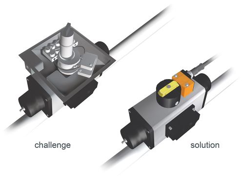
Challenge: Mechanical switchboxes have moving parts that can stick and break.
Solution: ifm’s sensor and target puck provide non-contact valve position feedback.
ifm’s IN sensors use standard inductive technology to provide non-contact detection of metal targets. A typical inductive sensor contains a ferrite core surrounded by a coil of wire to form an inductive circuit. An IN sensor incorporates two ferrite coils. These coils are positioned vertically inside the housing. The rotating puck, which is mounted on the actuator stem, contains two stainless steel targets positioned on the side of the puck, 90° apart, at different heights.
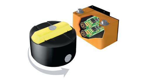
As the valve opens, the puck rotates, moving one of the targets in front of one ferrite coil. The coil senses the target and provides a positive signal of valve-open position.
When the valve closes, the puck rotates and moves the second target in front of the second ferrite coil. The coil senses the target and indicates a positive valve-closed position.
ifm offers these products in AC and DC voltage, with local solenoid switching, for hazardous locations and with integrated AS-i capability.
Selecting a puck kit
Select a puck kit according to the dimensions of your ISO Namur actuator. The X and Y dimensions show the position of the mounting holes and the Z dimension is the height of the actuator stem.
ifm makes two different types of target pucks. The basic puck is for standard 90 degree applications. The adjustable puck is for actuators with different target positions. The packages for higher stems include a spacer to raise the height of the sensor to match the targets on the puck.
