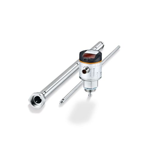
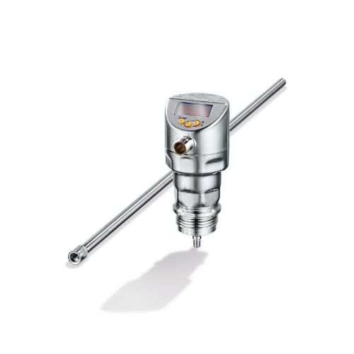
LR guided wave radar sensors
Are your float switches sticking or breaking? Does your application require continuous level measurement?
The LR family of products for both industrial automation and sanitary applications provides all the advantages of reliable continuous level measurement at a very low price point. Alternative level solutions may offer a lower price but may not perform in challenging applications.
Mechanical float switches can stick due to deposits. Vibration tuning forks offer better performance, but multiple units are required to measure several level points. Traditional guided wave radar level sensors offer improved performance, but at a very high price point.
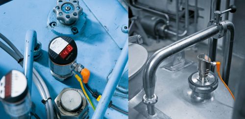
Applications
Balance tank level
Balance tanks are used to maintain a constant level of product above a pump inlet. What if you could save time and money with a flexible level solution?
The LR guided wave radar level transmitter is medium independent with probes that can be cut to length to fit any application. Settings can be easily adjusted at the sensor via raised pushbutton and bright LED display or remotely with IO-Link digital communication.
HPU tank level
LR sensors are used to continuously detect level in hydraulic power units. The level can be controlled within set limits using a switching output. The analog signal or IO-Link process value can be used to determine the current level in the tank.
Technology
The Guided Wave Radar (GWR) operating principle uses electromagnetic pulses in the nanosecond (microwave) range. The sensor head transmits the pulses and the pulses travel down the metal probe (guide). When the wave hits the medium, it is reflected back, collected by the metal probe, and guided to the sensor head. The time difference between the transmitting and receiving pulse (time-of-flight) is directly proportional to the distance measurement.

For proper decoupling of the radar pulse, a metal launching plate at least 6” square or 6” diameter is required. If the tank has a metal lid, that can act as the launching plate.

The image above shows a tank with a metal lid. No launching plate is required because the lid acts as the launching plate.

In a tank with a plastic lid, a metal launching plate is required. Shown is a flange that is at least 6" in diameter.

In an open tank, a launching plate is also required. An easy way to accomplish this is to bolt a flange onto a metal angle.
For oil-based media, the fluid surface does not reflect the radar pulse. Rather, it is dispersed into the media. To intensify and contain the signal, we must use a coaxial tube accessory.

When using the coaxial tube, the launching plate as described above is not necessary. This makes mounting easier. However, bridging between the probe and coaxial tube due to solids, emulsions, etc. can cause false level indication. The coaxial tube can be used with water-based media as well and the tube can be cut to length to match the probe.
Features:
- 3A authorized Clean-Out-of-Place (COP) design for some models
- Pressure rating up to 580 psi for some models
- 316L materials of construction
- Immune to dust, fog and steam
FAQs
Q. Are there any mounting restrictions?
A. The LR must be surrounded by metal at the mounting threads. This allows the radar pulse to de-couple from the electronics and travel down the probe. For installation in closed metal tanks, the metal lid of the tank performs this function. For open tanks, a metal launching plate must be installed on the bottom of the LR. Refer to the technology overview above for details.
ifm makes flanges which can be bolted to a metal tank lid and assures the threads of the sensor are flush (E43206 for LRx3xx sensors and E43201 for LRx0xx sensors.) However, the flanges are not large enough to qualify as a launching plate for open or plastic tanks. In this case, we offer a new launching plate (E43381 for LRx3xx sensors and E43380 for LRx0xx sensors.)
Please refer to the installation instructions for the LR sensors for other mounting restrictions.
Q. What is the purpose of the coax tube? Does the coax tube work with all LR sensors?
A. When the LR is used in water-based applications, more than 90% of the pulse is reflected back from the fluid surface to the sensor. The microprocessor can collect the reflected pulse and using time-of-flight, evaluate how long it takes the pulse to return to the sensor. With low dielectric fluids such as oil, the fluid surface does not reflect the pulse and instead, the pulse is dispersed into the media.
In order to intensify the returning signal, a coaxial tube is used to surround the probe, “contain” the radar pulse, and reflect it back to the sensor properly.

Not all LR sensors can be used with a coax tube. In addition to the mechanical change the coax tube offers, the sensor itself required firmware changes. Only the LR sensors with G3/4 BSPP process connectors (LRx0xx) have been equipped with these changes. However, there are coax tubes with external mounting threads that are ¾” NPT or G3/4 BSPP.
Q. What are the pros and cons of using a coax tube?
A. As seen above, coax tubes are required when using low dielectric liquids. They can also be used with water-based liquids.
Because the coax tube focuses the radar pulse, there is no need for a launching plate and the sensor can be mounted as closely to a wall or other internal obstruction without affecting the operation of the sensor. This makes the use of a coax tube very attractive.
For applications with mineral deposits, particulates, grinding swarf, etc., there is a possibility of bridging between the probe and coax tube. Because of the lubricity of oil, bridging is not likely to occur; it is more likely to occur when using the coax tube with water-based media.
Q. How does the LR react with foam?
A. It really depends on the type of foam.
- Light foam – slows down the radar pulse, resulting in a level reading that is slightly lower (1 – 2 cm) than the actual liquid level.
- Medium foam – the foam level is measured as the actual tank level.
- Dense foam – the foam can absorb the radar pulse completely, preventing measurement of level.
Q. How can I overcome issues with foam?
A. The most assured way is to prevent the foam from coming in contact with the rod. The LR can be installed in a bypass or stand pipe. Please refer to the installation instructions for required dimensions of the bypass and stand pipe.

Q. Does build up on the probe cause issues?
A. When used with water-based fluids and probe alone (no coax tube), build-up can be ignored. The radar signal is strong enough to go around the build-up and continue to travel down and up the probe. Testing should be done to determine actual performance in the application.

Q. Can I make my own probes and coax tubes out of different material for chemical compatibility?
A. Yes, but the LR sensors are calibrated assuming specific dimensions for probes and coax tubes. Please use the CAD drawings that are available online and follow the dimensions closely. The probes and coax tubes can be made of any metal that is compatible with your media. Ensure the LR electronics are not exposed to any media that is not compatible.
A thin (1 – 2 mm) coating of a plastic material can be applied to the probes as well. ifm does not offer this service.
Q. What is the difference between the LR2750 and all other LR sensors?
A. The LR2750 is designed specifically for challenging applications in the process industry. Applications such as balance tanks and filler bowls are difficult to solve with other technologies.
The LR2750 has a one-piece IP69K housing construction, high temperature and pressure ratings and sanitary design. This is a great solution for top down continuous level monitoring in process applications.
It uses a 3A-approved COP (Clean-Out-of-Place) design and foam suppression has been improved.
Different probes with a better surface finish are required for the LR2750, and coaxial tubes are not available.
Q. What is the difference between CIP and COP?
A. Clean-in-Place (CIP) is the removal of soil from product contact surfaces in their process position by circulating, spraying or flowing chemical solutions and water rinses onto and over the surfaces of the equipment to be cleaned.
Clean-Out-of-Place (COP) is used for components of the equipment that must be removed to be cleaned. To complete the required cleaning cycle, these devices are inspected and verified that all product contact surfaces are in proper condition.
Q. How is the LR2050 different from other LR products?
A. The LR2050 uses a newer gwr algorithm (similar to that of the LR2750) that produces a more stable output signal. It has an all stainless steel construction with an IP68/IP69K rating.
It uses the same probes and coax tubes as the other LRx0xx sensors, but because of the housing design, an extra thick seal is required. This seal is provided with the LR2050 sensor.
Q. What do I need to know to commission an LR2750 and LR2050?
A. To set up an LR2xxx, you need to select a probe option (Prob – note this is not an available option for the LR2750), input the probe length (LEnG), and select a media profile (MEdI). Although the tank adjustment (tRef) is often not needed, it is recommended to perform the tRef operation to ensure optimal performance. When performing a tRef, the sensor will require input of the teach distance.
The tRef allows for improved signal quality by removing tank obstructions from the radar pulse measurement zone. Obstructions such as inlet pipes (as shown in the illustration) can cause false signals that interfere with the reflected level signal. Most signal reliability issues are associated with the connection mounting and the first few inches of the installation.

When planning to use tRef the following points need to be considered:
- The minimum probe length is greater than 250 mm
- The max probe length is 1750 mm (max = L – 250), noting that you cannot use the tRef function on the bottom 250 mm of any probe
- You must enter the probe length to be adjusted (min. 10 mm)
- A safety distance “b” of at least 250 mm must be maintained between the tank level or rod end when programming the tRef function
- Installation distances to tank wall, bottom, and obstructions is reduced when using tRef (20, 10, and 20 mm respectively)
Keep in mind that in most cases it is only necessary to tRef the top 25 mm to 150 mm of the installation.
Example: 450 mm probe length; amin = 10 mm; amax = 200 mm (450 – 250 mm).
Therefore you can tRef between 10 and 200 mm of the probe length, making sure you observe the minimum safety distance “b” of 250 mm to the end of the probe or liquid level when programming the tank adjustment.