- SU Puresonic flowmeter
- Setup and support
- Device configuration
SU Puresonic: Simple parameterization via software or display
The following video guides you through key programming steps for the SU Puresonic flow meters. More details can be found below on this page or in the operating instructions on the the product datasheet page under the Downloads tab. You can read the video transcript here.
You can also visit our installation instructions or FAQs page. Should you need additional support, feel free to contact our service center at 888-704-0702 and speak to one of our applications engineers.
Programming setup for the SU ultrasonic flow meter series
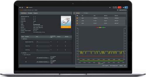
moneo | configure software
moneo | configure is a user-friendly software package that enables easy programming and visualization of all ifm IO-Link enabled sensors (V1.0 and V1.1) as well as other manufacturers' IO-Link enabled sensors (V1.1). The software can be downloaded here: moneo | configure.
moneo | blue software
moneo | blue is an app that runs on your Apple or Android smart phones and provides access to all parameters, process values and diagnostics from all sensors connected to an IO-Link master. The Bluetooth™ adapter, EIO330, connects to one port of the IO-Link master and the app can be downloaded free of charge from the Apple App Store or from Google play.

All of ifm's process sensors, including the SU ultrasonic flow meters, use similar terminology for programming. We highlight the features used most often here. Refer to the Operating Instructions manual found under the "Downloads" tab at the product datasheet page for more details on these and other features.
Switching outputs
-
Hno -- hysteresis normally open: Output turns on when the set point (SP) is reached and stays on until the flow rate drops below the reset point (rP)
-
Hnc -- hysteresis normally closed: Output turns off when the set point (SP) is reached and stays off until the flow rate drops below the reset point (rP)
-
Fno -- window normally open: Output turns on when flow rate is between the high limit (FH or SP) and low limit (FL or rP)
-
Fnc -- window normally closed: Output turns off when flow rate is between the high limit (FH or SP) and low limit (FL or rP)
Analog outputs
-
ASP -- analog start point: The flow rate where the analog signal equals 4 mA (or 0 VDC in some models)
-
AEP -- analog end point: The flow rate where the analog signal equals 20 mA (or 10 VDC in some models)
-
MAW -- initial value of the non-scaled measuring range
-
MEW -- final value of the non-scaled measuring range
The chart shows how the analog signal and display information changes when the flow rate is above / below the scaled or non-scaled measuring ranges. This feature is useful for your process control and troubleshooting issues.
The minimum scaled measuring range is available on the product datasheet.
Pulse output
-
ImPS -- pulse value: The volume of flow required for each pulse
-
ImPR -- repeating pulse: When set to yes, meter provides a pulse with each volume of flow specified by ImPS; when set to no, meter provides only a single pulse when the flow volume specified by ImPS is reached.
Pulse output vs. flow direction
-
FPro = 0+: Pulses are counted only when the flow is in the positive direction (negative flow is ignored)
-
FPro = -+: Pulses are counted in both flow directions. If flow is in the negative direction, an equal amount of flow in the positive direction must occur before the pulse output resumes.
The SU ultrasonic flow meters include a TFT display that shows flow rate, temperature, total flow and signal quality all at a glance. Other display indications:
- LED for switching status of output 1
- LED for switching status of output 2
- Diagnostic LED (green / blue / red)
- Display showing current process values or menu / parameters for setup
- Buttons for changing views and for parameterization

| 1 | Press Enter (E) once to enter programming mode. |
|---|---|
| 2 | Press Up or Down arrow (U/D) to view parameters or additional menus. |
| 3 | To change setting, press Enter (E) and then Up or Down arrow (U/D) and hold until the progress bar completes. Then press Up or Down arrow (U/D) to toggle through options. |
| 4 | When desired value is reached, press Enter (E) to confirm the setting. |
The following illustrate the most common programming required for flow meter applications. Refer to the Operating Instructions manual found under the "Downloads" tab at the product datasheet page for more details on these and other features.
Change units of measure
| 1 | Press E to enter programming mode. |
|---|---|
| 2 | Press D until "EF" extended functions is displayed. Press E to confirm. |
| 3 | Press D until "CFG" configuration is displayed. Press E to confirm. |
| 4 | "uni.F" units of measure for flow is displayed. Press E to confirm. |
| 5 | Press U/D to change to the desired units of measure. |
| 6 | "unit.T" units of measure for temperature can be changed in the same manner. |
| 7 | Press E to confirm. After 30 seconds, the meter returns to normal run mode. |
| 1 | Press E to enter programming mode. |
|---|---|
| 2 | Press D until "EF" extended functions is displayed. Press E to confirm. |
| 3 | Press D until "OUT2" output 2 is displayed. Press E to confirm. |
| 4 | Press D until "ou2" is displayed. Press E to confirm. |
| 5 | Press D until "ASP2" is displayed. Press E to confirm. |
| 6 | Press U/D to enter the value representing the analog start point (4mA). Press E to confirm setting. |
| 7 | Press D until "AEP2" is displayed. Press E to confirm. |
| 8 | Press U/D to enter the value representing the analog end point (20mA). |
| 9 | Press E to confirm setting. After 30 seconds, the meter returns to normal run mode. |
Note that the minimum distance between ASP and AEP is 20% of the final value of the measuring range.
| 1 | Press E to enter programming mode. |
|---|---|
| 2 | Press D until "EF" extended functions is displayed. Press E to confirm. |
| 3 | Press D until "OUT1" output 1 is displayed. Press E to confirm. |
| 4 | Press D until "ou1" is displayed. Press E to confirm. |
| 5 | Press D until "ImP" is displayed. This is the pulse output setting. Press E to confirm. |
| 6 | Press U until "ImPS" is displayed. This is the volumetric pulse value. Press E to confirm. |
| 7 | Press U/D to set the decimal point. Press E to confirm. |
| 8 | Press U/D to set the volume per pulse. Press E to confirm. |
| 9 | Press D until "ImPR" is displayed. Press E. Set to "YES" for a pulse every time the volume set above flows through the meter. Set to "NO" for a high pulse once the volume above flows through the meter. |
| 10 | Press E to confirm setting. After 30 seconds, the meter returns to normal run mode. |