- SU Puresonic flowmeter
- Setup and support
Installing the SU ultrasonic flow meter
Congratulations on selecting the right SU ultrasonic flow meter for your application! This page features our installation guidelines, and you can keep reading for device configuration instructions.
Should you need additional support, please contact our service center at 888-704-0702 and speak to one of our applications engineers.
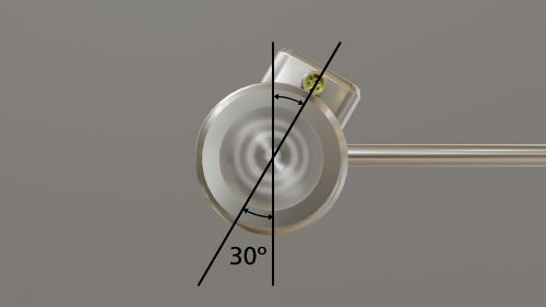
Direction of flow
The arrow etched on the sensor housing indicates flow direction.
- The display indicates flow in the opposite direction of the arrow with a minus sign.
- Analog and switching signals are based on flow only in the direction of flow. These signals cannot be set for flow in the opposite direction.
- When using IO-Link, the process value includes the direction of flow, meaning negative flow can be measured and transmitted.
- The direction of flow can be changed in the parameter setting of the sensor. If the direction of flow is changed, apply the enclosed label to the housing of the sensor.
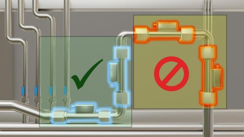
Recommended (Green) and Not Recommended (Yellow) installation locations.
Straight pipe run
Structures in the pipe—such as bends, valves, reducers, and similar elements—can affect the performance of the unit. To ensure accurate measurement, maintain proper distances between the sensor and any sources of flow disturbance. As a best practice, allow a specified number of pipe diameters upstream and downstream from the flow meter.

| Part number | DN (mm) |
A (inlet) | B (outlet) |
|---|---|---|---|
| SU6xxx SUH1xx SU7xxx SUH8xx SU8xxx SUH2xx SU9xxx SU2xxx SUH4xx |
DN15 DN15 DN20 DN20 DN25 DN25 DN32 DN50 DN50 |
5 x D | 1 x D |
| SUH5xx SUH6xx SUH7xx |
DN65 DN80 DN100 |
15 x D | 3 x D |
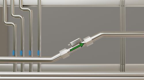
Electrical grounding
A solid reference value is required for proper function. Most metal piping systems are installed such that they are grounded to the building steel and therefore, to a solid earth ground. This is not the case when the piping system is plastic. For plastic or ungrounded piping systems, always provide a path to earth ground. Part number E40234 makes grounding the sensor effective and easy.
Caution
If the medium temperature is above 50 °C / 122 °F, parts of the housing can heat up to over 65 °C / 149 °F. Protect against risks of burns and unintentional contact with flammable substances. Apply the warning label supplied with the sensor to the cable near the housing.