Select the perfect photoelectric sensor
Photoelectric sensors are good for applications that require long sensing ranges, detection of small targets or a wide variety of target materials, high speed sensing, distance measurements, or immunity to high frequency electromagnetic noise. ifm has been offering photoelectric sensors since 1980. Over the years, our products have become smaller yet more powerful and precise. Versions are available with visible red and infrared light sources for general applications and laser light sources when more precision is required. Available technologies include through-beam, retroreflective, diffuse, and background suppression types.
Use the 'Select by application' tables below to explore options for error-proofing, conveying, high-pressure cleaning, and more. Read about the underlying measuring principles and technology of a sensor group by finding the orange “Learn More” row.
Laser distance sensors and optical sensors for error-proofing
| Lasers with distance measurement | Error-proofing | ||||||||
|---|---|---|---|---|---|---|---|---|---|
 |
 g g |
 |
 |
 |
 |
 |
 |
||
| Precision laser, OGD M18 cube |
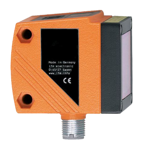
Precision laser, O6D |
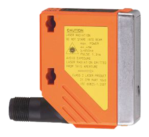
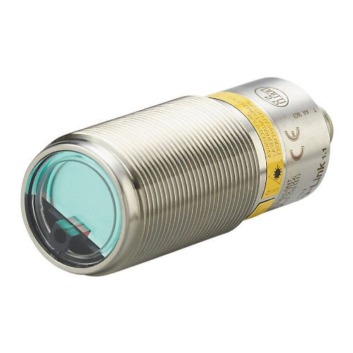
Long range laser, O1D rectangular |
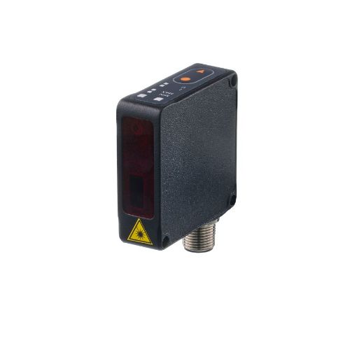
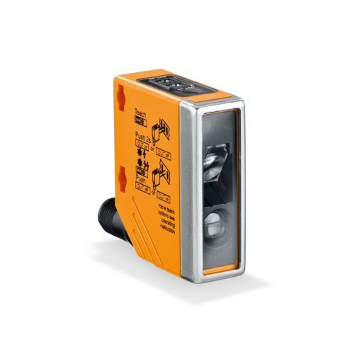
Laser, O5D rectangular |
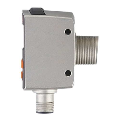
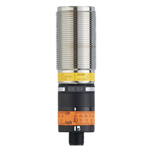
Laser, OID M30 barrel |
Laser for food and beverage, OID M30 barrel |
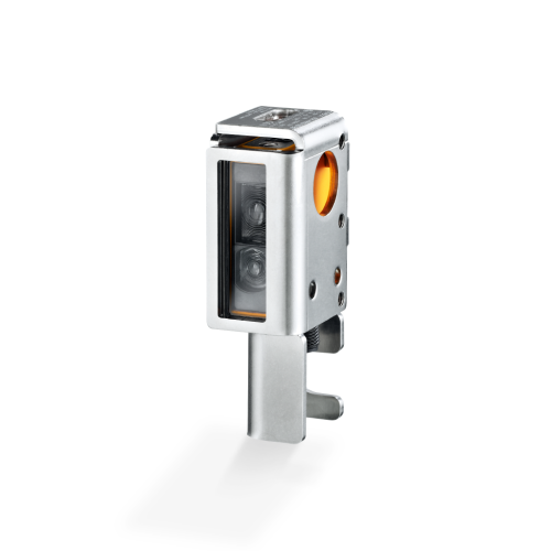
PMD Laser Line Profiler, OPD |
High-accuracy laser, OMH |
||
| Sensing range | 2 m | 3 m | 10 m | 2 m | 2 m | 2 m | 300 mm | 500 mm | |
| Accuracies at various ranges | |||||||||
 |
@300 mm | 3 mm | 5 mm | 14 mm | 12 mm | 12 mm | 12 mm | 0.5 mm | 1 mm |
| @ 500 mm | 4 mm | 5 mm | 14 mm | 15 mm | 15 mm | 15 mm | - | 3 mm | |
| @ 1 m | 5 mm | 10 mm | 14 mm | 15 mm | 15 mm | 15 mm | - | - | |
| @ 2 m | 10 mm | 20 mm | 14.5 mm | 30 mm | 25 mm | 25 mm | - | - | |
| @ 10 m | - | - | 47 mm | - | - | - | - | - | |
| IP Rating | IP65,IP67 | IP65,IP67 | IP67 | IP65,IP67 | IP65,IP67 | IP65,IP67,IP68,IP69K | IP65 | IP65,IP67 | |
| Interface | Pushbuttons, IO-Link |
Pushbuttons, IO-Link |
Pushbuttons, IO-Link |
Pushbuttons, IO-Link |
Setting ring, IO-Link |
Set via IO-Link only | Pushbuttons, IO-Link |
Pushbuttons, IO-Link |
|
 |
Display |  |
 |
|
|
|
|
|
|
 |
For industrial automation, Type OGD |
For industrial automation, Type O6D |
For long range applications, Type O1D |
For applications with reflective environments, Type O5D |
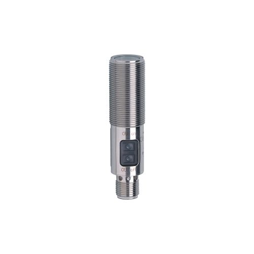
With adjustment dial, Type OID |
For harsh environments, Type OID |
For object profile checking, Type OPD |
With 0.01 mm resolution, Type OMH |
|
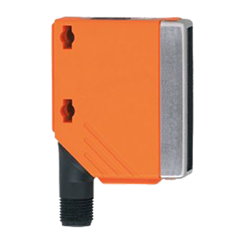
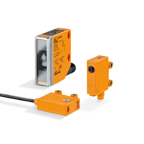
General purpose photoelectric sensors
| General purpose industrial applications | ||||||
|---|---|---|---|---|---|---|
 |
 |
 |
 |
 |
||
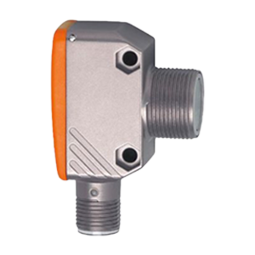
| OG, M18 barrel housing |
OG, M18 cube housing |
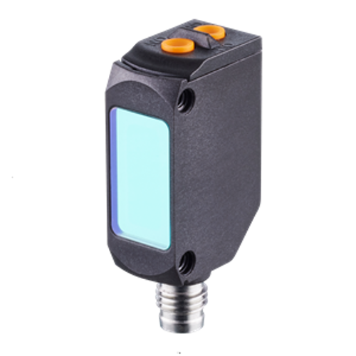
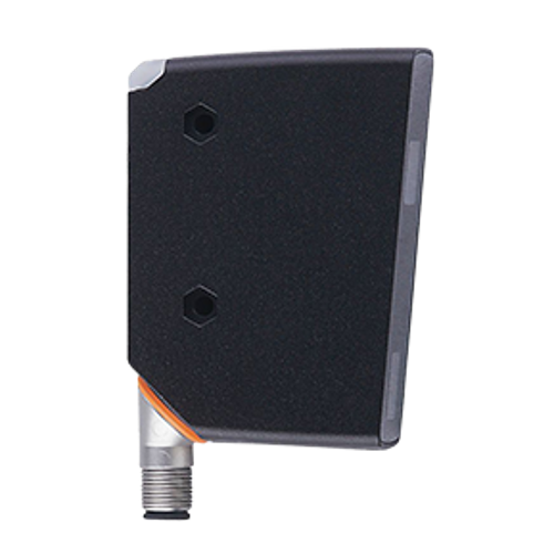
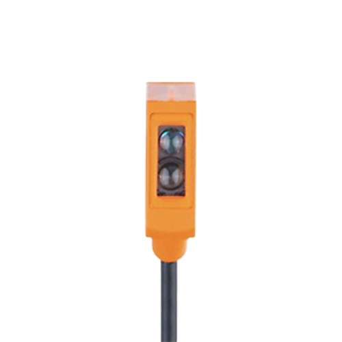
O8, miniature rectangular housing |
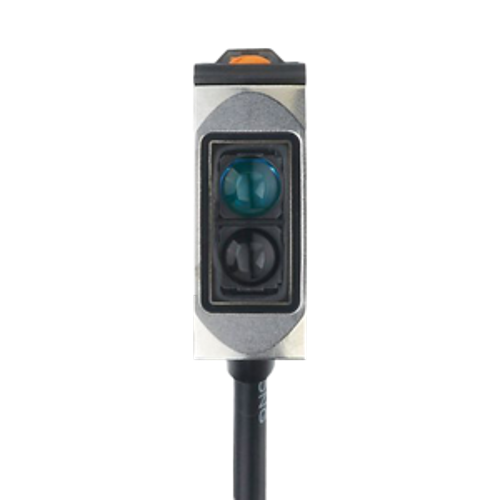
O6, small rectangular housing |
O5, rectangular housing |
||
| Technology available with sensing ranges | ||||||
| Background suppression | 300 mm | 200 mm | 80 mm | 200 mm | 1.8 m | |
| Retro-reflective | 5 m | 4 m | 1.8 m | 5 m | 10 m | |
| Through-beam | 25 m | 20 m | 3 m | 10 m | 25 m | |
|
Accuracy (Min target-to-background distance at max range) |
25 mm | 7 mm | 4 mm | 4 mm | 200 mm |
| IP rating | IP65, IP67, IP68, IP69K | IP65, IP67, IP68, IP69K | IP65, IP67 | IP65, IP67, IP68, IP69K | IP65, IP67 | |
| Interface | Potentiometer, Pushbuttons, Fixed range |
Pushbuttons, Fixed range |
Fixed range | Potentiometer | Pushbuttons | |
|
For industrial or high pressure cleaning applications, Type OG barrel | For industrial or high pressure cleaning applications, Type OG cube | For short range precise applications, Type O8 | For industrial or Food and Beverage applications, Type O6 | For industrial automation, Type O5 | |
Additional photoelectric products


Technology overview
| PMD time-of-flight | Through-beam | Polarized retro-reflective | Diffuse with background suppression | Diffuse with no background suppression | |
|---|---|---|---|---|---|
| Sensing range | |
|
|
 |
|
| Ability to detect small targets | |
|
|
|
|
| Conveying applications | |
|
|
|
|
| Harsh environments (water and dust) |
|
|
|
|
|
| Accuracy | |
|
|
|
|
| Hardware cost |  |
|
 |
 |
|
| Installation cost | |
|
|
|
|
| : Ideal application |
: Do not use in application |
: Proceed with caution |
PMD time-of-flight technology
With the exception of using a laser light source, standard laser sensors operate the same as photoelectric sensors using visible red or infrared light sources. Many of ifm’s laser sensors use PMD time-of-flight to calculate distance due to a phase shift in the light waves.
PMD (Photonic Mixer Device) determines the distance between the sensor and object (and the sensor and the background) by measuring the time it takes for the light to travel from the sensor to the target and back again. Light waves propagate from the laser light source. When the light bounces off the target, the phase pattern shifts and the shift is directly proportional to the distance.
ifm’s OGD, O1D, O5D and OID laser distance sensors all use this technology.
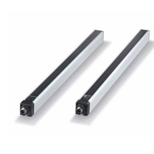
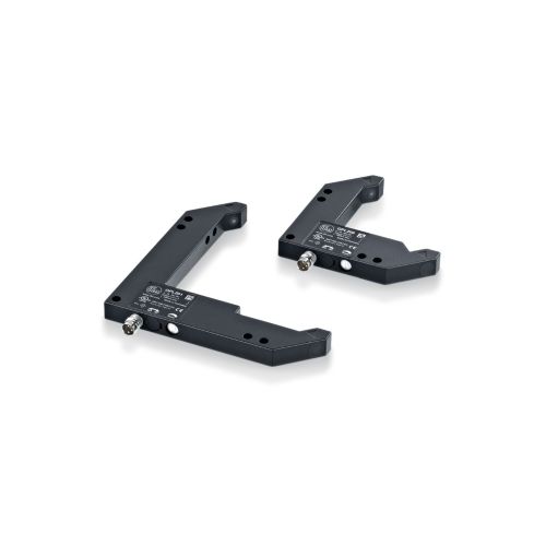
Through beam technology
Also known as through beam / thru-beam pairs. The transmitter and receiver are packaged in separate housings and are mounted opposite each other. Light is sent from the transmitter lens and is picked up by the receiver lens

The output changes state when a target interrupts the beam and starves the receiver of light. As long as the target is large and solid enough to break the effective beam, the color, shape, angle, reflectivity and surface finish will not affect the application. This makes them more reliable than diffuse sensors, which depend on light reflecting off the target.

The effective beam is uniform in diameter and is approximately equal to the diameter of the transmitter and receiver lenses. So long as the target is at least as big as the effective beam, the output will switch when the target breaks the beam.
Installation considerations:
Retroreflective technology with polarizing filter
The transmitter and receiver are packaged in the same housing and mounted opposite a reflector. Light is sent from the transmitter lens, bounces off the reflector and returns to the receiver lens.

As with thru-beam sensors, the output changes state when a target interrupts the beam and starves the receiver of light. As long as the target is large and solid enough to break the effective beam, the color, shape, angle, reflectivity and surface finish will not affect the application. This makes them more reliable than diffuse sensors, which depend on light reflecting off the target.

The effective beam of polarized retroreflective sensors is cone-shaped. Near the sensor, the beam is approximately the size of the transmitter lens. Near the reflector, it is the size of the reflector. This means that smaller objects can be detected when close to the sensor, but not necessarily when close to the reflector.

Prismatic reflectors are required for polarized retroreflective sensors. By their design, these reflectors rotate the incoming light beam by 90 degrees. The sensors are equipped with polarizing filters over the lens so light waves are oriented in one direction only. The reflector rotates the light waves to match the orientation of the filter on the receiver.
Shiny targets may return high intensity light to the sensor, but since the light is not properly oriented, the shiny targets will not cause a false signal.
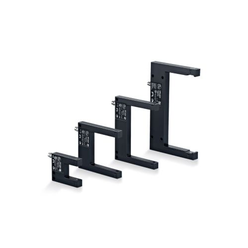
Diffuse technology
The transmitter and receiver in a diffuse sensor is located in the same housing. The transmitted light reflects back to the sensor from the target and the receiver evaluates it. It is important to carefully consider the characteristics of the target and the background behind the target when selecting the correct solution for an application. Diffuse sensors have much less excess gain than thru-beam pairs, but typically more than polarized retroreflective types.

The sensitivity of diffuse sensors is very high. Only 2% of the transmitted light energy reflected off the target will cause the output to switch.
Target influences:
Background interference
A diffuse sensor detects all light reflected into the receiver, regardless of its source. Light reflecting off the background appears the same as light from the target and is especially troubling when the background is more reflective than the target and when the target and background are very close together.
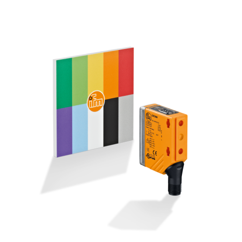
Diffuse technology with background suppression
These sensors are specially designed diffuse sensors that eliminate false tripping on the background behind the target. Several technologies suppress backgrounds including:

Fixed range
The position of the transmitter and receiver lenses are angled to create a detection zone. Objects in the detection zone reflect light into the receiving lens and are sensed. Objects outside the detection zone (either too close or too far) do not have the correct geometry to return light to receiver. This method is normally used for short range and is not adjustable.

Triangulation principle
This technology uses two receiving elements to obtain background suppression. Using a potentiometer for adjustment, a mirror is mechanically positioned to determine the point where one receiver detects the target and the other detects the background. The sensor is then adjusted halfway between these two points. The sensor evaluates the angle of the received light to determine if the light comes from the target or the background.

Diode array
This method is similar to the triangulation principle, except the receivers are a 63-diode array. The additional receivers allow for precise background suppression (i.e., the target and background can be very close). Diode array sensors are equipped with a microprocessor and programmed electronically via pushbuttons.
PMD time-of-flight
Understanding the electromagnetic radiation spectrum
To best apply photoelectric sensors, it is helpful to understand the electromagnetic radiation spectrum. ifm photoelectric sensors operate in the visible (primarily red) and infrared frequency ranges.

| Visible red light | Infrared light | Laser light | |
|---|---|---|---|
| Advantage(s) |
|
|
|
| Disadvantage(s) |
|
|
|
Terminology
Modulated light – light sent by the transmitter is pulsed at a frequency unique to each sensor family. The receiver is tuned to detect light modulated at this frequency and ignore ambient light from other sources.
Switching frequency – maximum speed at which a sensor will deliver discrete pulses as the target enters and leaves the sensing field. Simply, it is how fast the sensor can switch on and off when a target passes by.
See the first 2 images on the right, Total switching time (ts) = t1 and t2. Switching frequency (fs) = 1 / ts.
Contrast – the difference in color and brightness between two objects. White is the easiest color to detect and black is the hardest to detect.
Beam spot (or light spot) – the diameter of the transmitted light at a given distance. This dimension is usually shown on datasheets at the maximum range and it is a function of the transmitter lens angle of aperture.
Effective beam – the area of the light beam that must be completely interrupted for the sensor output to change state. Sensors that switch when the light beam is broken (i.e., through beam and polarized retroreflective sensors) have effective beams. Sensors that bounce light directly off the target (i.e., diffuse sensors) do not have effective beams.
Light operate (or light-on) – the output changes state when the receiver detects light.
Dark operate (or dark-on) – the output changes state when the receiver does not detect light.
Excess gain – the ratio of light energy received by the sensor to the energy required to change its output state. A gain value of 1 is the minimum required to switch the output. Anything above this threshold is considered excess gain. It is useful in determining proper operation of the sensor in contaminated areas.
| Minimum excess gain required | Operating environment |
|---|---|
| 1.5X | Clean air: No dirt build-up on lenses or reflectors. |
| 5X | Slightly dirty: Slight build-up of dust, dirt, oil, moisture, etc. on lenses or reflectors; lenses are cleaned on regular schedule. |
| 10X | Moderately dirty: Obvious contamination of lenses or reflectors, but not obscured; lenses cleaned occasionally or when necessary. |
| 50X | Very dirty: Heavy contamination of lenses; heavy fog, mist, dust, smoke, or oil film; minimal cleaning of lenses. |