- Compact speed monitors
- Setup and support
- Programming
Speed sensors: Programming
Programming
The following will guide you through the setup and programming steps for the compact speed monitors.
Operation and LED indications
| Device status | LED indication |
|---|---|
| Operating voltage is applied | Green (permanently on) |
| In the measuring range | Yellow (permanently on) |
| Outside the measuring range (UL) | Yellow (flashing) 2Hz, mark-to-space ratio: 1:1 |
| Outside the measuring range (OL) | Yellow (flashing) 2Hz, mark-to-space ratio: 1:1 |
| After power-on in the IO-Link mode = "NO DATA" (PDV=+32764) If no process data value is measured or max. 120s timeout. |
Yellow (flashing) 2Hz, mark-to-space ratio: 1:1 |
Using IO-Link, the compact speed monitors and be programmed for single point mode (hysteresis normally open or normally closed) or for window mode (where the output is switched between two points). The charts below depict the output functions for the various conditions.
Single point mode
Normally open (switch point logic = 1)
- SP1: switch-off point
- SP1 + hyst: switch-on point
- The “open” output status indicates that a set rotational speed has not been reached.

Normally open output behavior
Normally closed (switch point logic = 0)
- SP1: switch-on point
- SP1+hyst: switch-off point.
- The “closed” output status indicates that a set rotational speed has not been reached

Normally closed output behavior
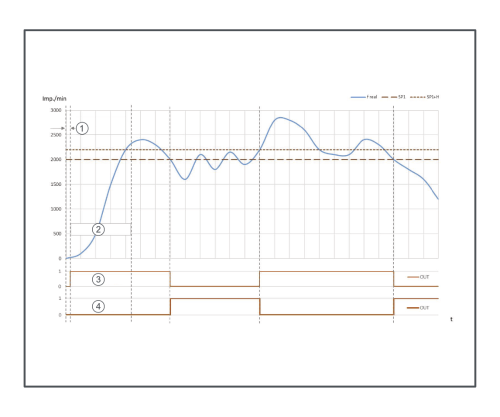
Function diagram for single point mode where 1 = power-on delay time, 2 = start-up delay time, 3 = output function normally open, 4 = output function normally closed
Window mode
Normally open (switch point logic = 1)
- SP1: switch-on point window
- SP1 + hyst: switch-off point
- SP2: switch-on point window
- SP2 + hyst: switch-off point

Normally open output behavior
Normally closed (switch point logic = 0)
- SP1: switch-off point window
- SP1 + hyst: switch-on point
- SP2: switch-off point window
- SP2 + hyst: switch-on point
Find more information on installing sensors for speed.

Normally closed output behavior

Function diagram for window mode where 1 = power-on delay time, 2 = start-up delay time, 3 = output function normally open, 4 = output function normally closed