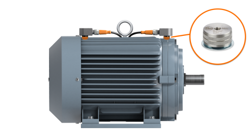
- 3-axis vibration sensor with IO-Link
- Setup and support
VVB 3-axis vibration sensor: Installation guidelines
Thank you for your purchase of a VVB 3-axis IO-Link vibration sensor. On the following pages, you will find information to help you install and integrate the sensor as well as answers to frequently asked questions.
Should you need additional support, feel free to contact our service center at 800-441-8246 and speak to one of our application engineers.
Mounting benefits of 3-axis vibration measurement
When measuring vibration, the optimal location is along the radial axis (horizontal or vertical) relative to the machine’s movement—ideally near the bearing on the drive end. Single-axis sensors often require precise mounting to align with a specific direction, which can limit options. In contrast, triaxial sensors capture vibration in all directions, giving greater flexibility. They allow for prioritization of solid, flat, and clean surface contact while still capturing the critical radial vibration data. See the examples below.
Motor

Sensor location is optional if the driven and non-driven ends are ≤750 mm apart; required if >750 mm.
Reducer
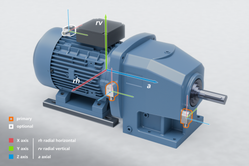
Sensor location is optional if the driven and non-driven ends are ≤750 mm apart; required if >750 mm.
Pump
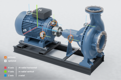
Sensor location is optional if the driven and non-driven ends are ≤750 mm apart; required if >750 mm.
Fan

Sensor location is optional if the driven and non-driven ends are ≤750 mm apart; required if >750 mm.
VVB3 mounting options
The vibration sensor can be flexibly mounted thanks to three measurement axes, with a range of mounting accessories providing added flexibility. It should be noted that the use of mounting accessories may affect the measurement.
Where? Ideally, a sensor is placed near each bearing seat.
How? The sensor should be screwed into a solid housing material or mounted using suitable ifm mounting accessories: