- PY pressure transmitter for insulated tanks
- Setup and support
PY20 insulated tank installation
Thank you for your purchase of a PY pressure transmitter. On the following pages, you will find information to help you install and program the sensor as well as answers to frequently asked questions.
For best performance of the PY family for insulated tanks, please follow the guidelines below.
Should you need additional support, feel free to contact our service center at 800-441-8246 to speak with one of our application engineers.
Adapter system
The PY20 family of sensors uses a flexible process connection system known as Aseptoflex Vario. A stainless steel fitting adapts from the G1 BSPP thread of the sensor to various tank spud installations.
Installing in insulated tanks
The animation below shows a typical installation into an existing insulated tank shell.
Sanitary installations with 3A authorization
Two key design features ensure that the sensor/fitting system maintains 3A authorization:
- O-ring seal between the sensor and the medium
This ensures a secure and hygienic connection, preventing any leakage. - Leakage port to veryify o-ring seal integrity
This feature allows for the monitoring of the o-ring seal to confirm its proper functioning.
Together, these features provide a safe and hygienic installation that is fully compliant with 3A standards.
Installation instructions:
- Ensure that the system pressure is removed, and the tank or pipe is drained before installation.
- Use a clamp and seal (not supplied by ifm) that is rated for the system's pressure.
- The tightening torque of the clamp should be according to the manufacturer's specifications.

O-ring seal
The o-ring provides a mechanical seal between the sensor and the medium. We offer o-rings in FKM and EPDM elastomers as well as a PEEK sealing ring. This PEEK ring provides longer stability compared to traditional elastomers that become hard and brittle over time.

Leakage port
The second design feature required for 3A authorization is a leakage port, or weep hole. When an o-ring is in place, the process medium will remain in the tank or pipe. If that o-ring is compromised, i.e., missing or damaged, the process medium will leak at the weep hole. This is an indication that the o-ring must be replaced.
Replace with one of the article numbers in the table below.
| Article | Material | Description / application | Supplied with: |
|---|---|---|---|
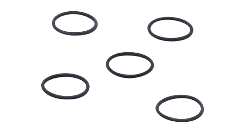 E30054 |
EPDM FDA compliant |
EPDM is the most common gasket material used in F&B applications and has a very good suitability with hot water / steam and both acidic / alkaline CIP fluids. This O-ring seals between the face of the process connection and the adapter. | Aseptoflex Vario adapter |
 E30123 |
FKM FDA compliant |
FKM is very suitable for oil applications as there is minimum swelling even with mineral oils, and it is the most common material for industrial applications with excellent chemical and high temperature resistance. | Optional accessory purchased seperately |
 E30124 |
PEEK FDA compliant |
PEEK is a more durable seal if devices are removed during cleaning process, has universal resistance to chemicals, and is more stable than elastomers that become hard and brittle over time. | Optional accessory purchased seperately |
Optimal sensor and atmospheric vent orientation
To avoid build-up on the measuring cell, avoid placing the measuring face horizontally, facing up. For example, in the lower secction of the pipe or tank (positions 4 or 5).
The PY is a relative pressure sensor; therefore, it requires a reference to the atmospheric pressure. This vent is covered to protect against ingress and build-up, which will affect the accuracy of the sensor.
Ensure the atmospheric vent is in a vertical position, or no more than a 30-degree angle if installed horizontally, to allow proper flow of washdown media.
For installations in high humidity or where media coats sensors:
- The sensor’s atmospheric vent must be able to breathe freely for the sensor to measure accurately.
- Vent tubes can be installed to relocate the atmospheric vent to a safe area or position the vent in the appropriate position when sensor cannot be rotated.
- This is primarily a concern with lower pressure measurements in tank level applications since the vent provides the atmospheric reference for the relative pressure measurement.
Optional vent accessories for additional protection
In most cases, following the guidelines for vent orientation is adequate to guard against ingress through the vent. However, for applications with particularly difficult environmental conditions or installations where the ideal alignment is not possible, the following optional accessories can be used to protect the atmospheric vent.
| 1 | E30483 | Replacement filter cover and ventilation membrane | 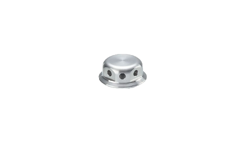 |
|---|---|---|---|
| 2 | E30148 | Closed vent cap: Only recommended for applications ≥ 25 bar or application temperature is constant. | 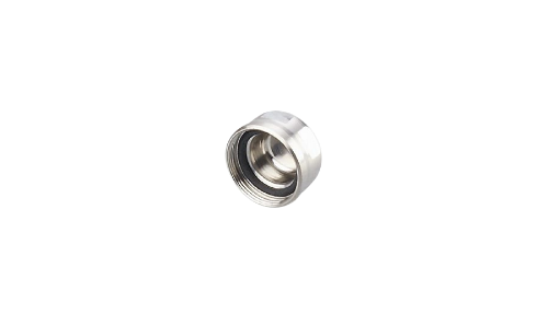 |
| 3 | E30139 | Filter cover with tube fitting and vent tube that can be located in a protected and dry area*. | 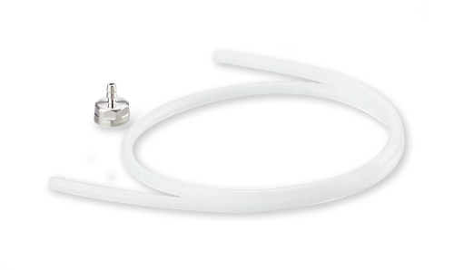 |
| 4 | E30467 | Filter cover with rotatable push to connect fitting, additional plug-in filter cover, and vent tube. Recommended for applications where the end of the vent tube cannot be protected or where chemically demanding external cleaning is conducted. | 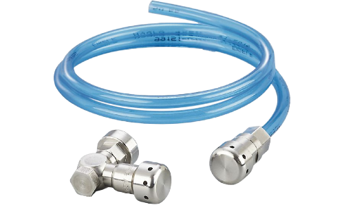 |
The following interactive animation shows how to connect the various vent accessories. The vent for the PY is similar to that shown in animation.