- Conductivity – a new approach
- Setup and support
Installation guidelines
For the best conductivity sensor operation and reliability in various use cases, follow the guidelines explained below and in our published programming and operating instructions.
Should you need additional support, feel free to contact our service center at 888-704-0702 and speak to one of our applications engineers.
All LDL sensors
Pipe size / recommended fittings
| Pipe size | 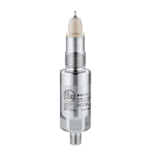 LDL100 |
 LDL200 |
 LDL201 |
|||||
|---|---|---|---|---|---|---|---|---|
| 1" | 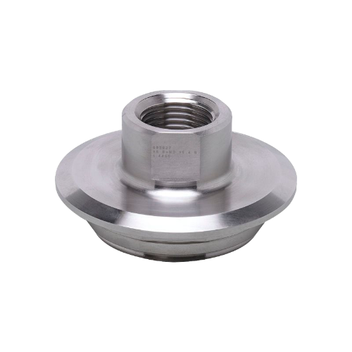 E43306 Type F Varivent fitting |
Not recommended | Not recommended | |||||
| 1-1/2" | 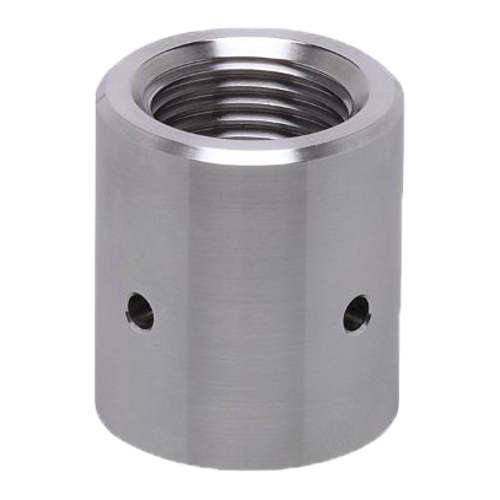 E43310 weld fitting 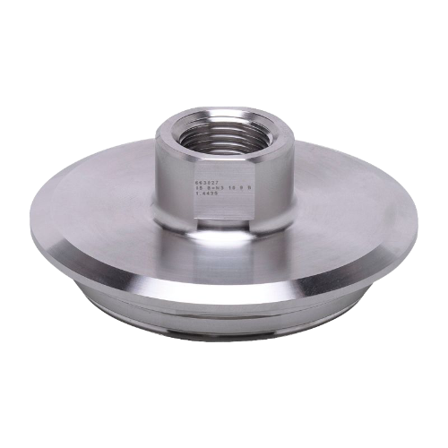 E43307 Type N Varivent fitting |
|||||||
| 2" | 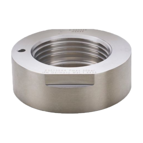 E30130 weld fitting 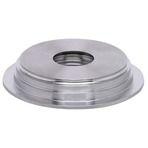 E33229 Type N Varivent fitting |
|||||||
| ≥ 2-1/2" | 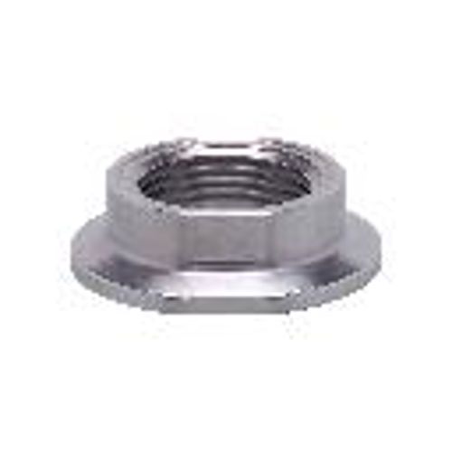 E33208 1-1/2" Triclamp fitting E33209 2" Triclamp fitting |
|||||||
Orientation
Preferable mounting is just before or in a vertical pipe with flow going up to ensure a full pipe. When installed in a horizontal pipe, install the sensor at a maximum of 45° from horizontal to avoid the influence of air bubbles or deposits but ensure the medium is in contact with the sensor tip.
Top mounting may be acceptable under the following conditions:
- Pressurized pipe
- Full pipe
- No air bubbles
Straight pipe runs
To eliminate disturbances caused by bends, valves, pipe reductions, etc., provide at least 5 times the pipe diameter of straight run before and after the sensor.

LDL100 only
Mounting in plastic pipes
The design of the LDL100 requires both electrodes to be in contact with the medium. Therefore, a metal fitting such as E43313 (G1/2 BSPP x ¾” NPT) is recommended. The LDL200 is not affected due to its design.
LDL2xx only
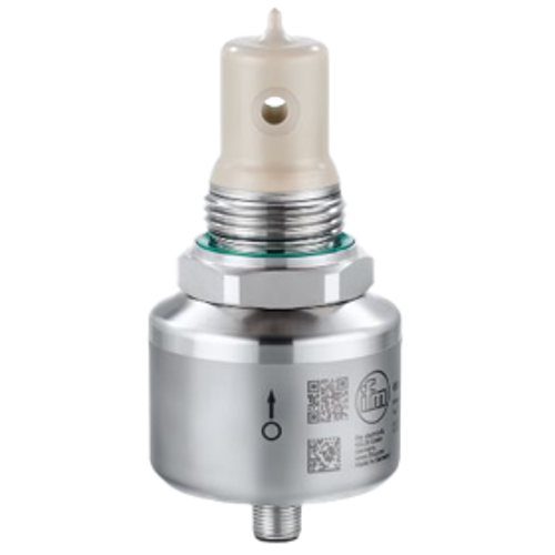
Alignment of measuring channel
The measurement channel of the LDL2xx must be installed parallel to the direction of flow. An alignment mark is laser etched on the body of the sensor indicating the correct orientation in the pipe.
Tank mounting
Ensure the measuring channel (1) is vertical to prevent air bubbles and deposits.
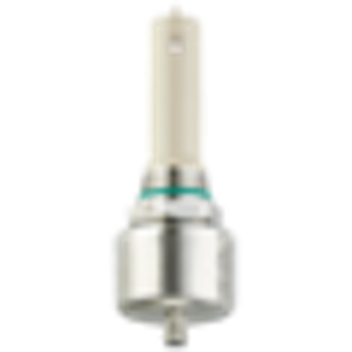
LDL201 only
Tri-clamp mounting
The LDL201 is designed for use with tri-clamp fittings, but you must ensure adequate space to accomodate the insertion depth of 76 mm (3"). When using a standard instrument (short) tee with tri-clamp fittings, a minimum line size of 2-1/2" is required. See diagram below.
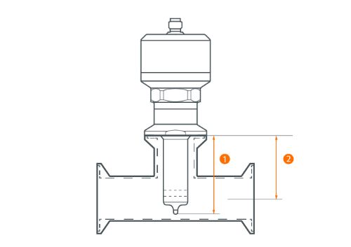
1: Length of probe to sealing edge of tri-clamp fitting = 3" (76 mm); 2: Distance from top of tee to centerline = 1.88" (47.6 mm)