- Energy optimization
- Compressed air
- Get started
Create an air or gas leak detection process: Nine steps
We have established that leaks in your systems create losses of 30% or more and that loss is expensive. The following details 9 general steps to implement a successful real-time gas leak detection process using a flow meter for compressed air and industrial gases. It may seem daunting, but the ROI is worth it!
Guide: How to reduce leaks in compressed air systems
The nine-step process to reduce leaks in a compressed air system is:
- Establish compressed air usage baseline
- Estimate the loss due to leakage
- Determine cost of leaks
- Identify leaks
- Document leaks and prioritize leak repair
- Adjust compressor controls
- Document repairs
- Compare results to baseline and publish
- Start over
Let's look at these steps in more detail:
| Step 1 - Establish compressed air usage baseline |
The most reliable method to establish your baseline usage is to install one or more flowmeters.
- Most popular today is a thermal mass flowmeter that uses two temperature sensors -- one heated and one static.
- Mass flow is proportional to the amount of power required to keep a constant temperature difference between the sensors.
- Must be placed in a dry airstream, since moisture in the air will affect the measured flow rate.
- Output is scfm (standard cfm) vs. acfm (actual cfm). Refer to this FAQ for an explanation of the difference.
Most high-volume leaks are likely not on the supply side in your main air headers, since there are fewer pipe connections. However, installation in these lines will help provide an overall usage baseline.
Leak are most likely in branch piping to several machines (zone monitoring) or at the end-use location (individual machine monitoring). To divide your plant into zones, consider the following:
- pipe size
- air flow rates
- number of potential leak points
- number of use points
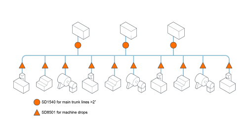
Insertion-style meters in larger pipes, inline-style meters for smaller pipes
| Step 2 - Estimate the loss due to leakage |
Once you establish a compressed air usage baseline, you can estimate the amount of that usage that is based on leaks. As stated earlier, 20-30% of usage is attributed to loss.
If you have actually identified leaks in this step, refer to the table below for estimated cfm loss per leak.
Estimated air flow losses due to leakage
| Hole size | Compressed air pressure | ||
|---|---|---|---|
| 80 psi | 90 psi | 100 psi | |
| 1/16" | 3.2 cfm | 3.5 cfm | 3.8 cfm |
| 1/8" | 12.7 cfm | 14.1 cfm | 15.4 cfm |
| 1/4" | 51 cfm | 56 cfm | 62 cfm |
| Step 3 - Determine cost of leaks |
To put a dollar amount to your leaks, you need to know:
- Estimated cfm loss from step 2
- kW / cfm generated from compressor manufacturer's specification
- Annual operating hours
- $ / kWh electric rate
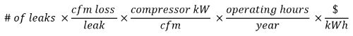
Use calculation to determine the cost of leaks
| Step 4 - Identify leaks |
Traditional leak detection methods are all labor intensive and hit-or-miss.
- Listen and feel
- Soapy water around joints
- Utrasonic leak detector
When an SD flowmeter is installed in a zone or machine
- Measure compressed air usage when equipment is idle
- Provides trend data to monitor machine performance over time or compare the consumption of identical machines
- Helps point to the area of leaks so maintenance team can focus on fixing leaks rather than identifying them
| Step 5 - Document leaks and prioritize leak repair |
Document the location, type, size and estimated cost of the leak. Prioritize repair.
- Largest leaks for biggest savings
- Easiest leaks to reach for quick start
- Leaks most affecting machine performance
| Step 6 - Adjust compressor controls |
Compressed air system controls regulate system pressure by matching supply with demand. As you repair leaks, your compressed air demand will decrease. You will likely need to adjust your control strategy for start / stop, load / unload, etc. A well-established leak detection program can eliminate the need for an additional compressor by optimizing the existing system.
| Step 7 - Document repairs |
How many leaks were repaired? What size were the leaks? This information will be used in the next step to quantify savings. Documentation will also help you identify leaks that may recur at certain operations in your manufacturing process. Knowing this will allow you to examine your process for overall improvements.
| Step 8 - Compare results to baseline and publish |
What trends do you now see in your consumption? Use the difference between your original consumption and new consumption to calculate energy savings by making your documented repairs.
Be sure to publish these results to the utilities / facilities manager at your plant. Showing these savings will solidify buy-in for your leak detection process.
| Step 9 - Start over |
Processes are not a series of discrete steps; rather they are continuous. Repeat the cycle of improvement and monitor the overall efficiency of your equipment.