- SI flow sensors
- Setup and support
- Installation guidelines
Installation guidelines - SI series flow switches
For best performance of the SI family of flow sensors, please adhere to the following guidelines. Should you need additional support, feel free to contact our service center at 888-704-0702 and speak to one of our applications engineers.
Insertion depth
As seen in the Technology section, the SI sensor monitors the difference in temperature of two RTDs – one located at the tip that reacts as the flowing medium conducts heat away, and one located ~12 mm above that provides the medium reference temperature.

To account for any medium temperature changes, the tip of the sensor must be located within the flowing medium. Be sure to take this into consideration when choosing your mounting accessories.

Pipe mounting
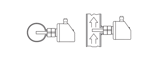
To help ensure the sensor tip is surrounded by the medium, always mount the sensor in a vertical section of pipe with flow going up. This method guarantees the pipe is full. If horizontal mounting is the only option, mount at an angle in case the pipe may not be full.

Recommended mounting
If the pipe is guaranteed to be full, the sensor may be mounted from the top.
Because of the principle of operation, build-up on the sensor tip affects heat conduction. If the medium is free from build-up, horiztonal mounting from the bottom is possible.
Be sure to thoroughly test the sensor in these situations.

Conditional mounting
Two mounting situations that are not recommended in any case are:
- Sensor tip in contact with the opposite pipe wall. This will adversely affect the heat conduction process.
- In a pipe with downward flow that is open to atmosphere and not a closed loop system. The velocity profile in such a situation is not repeatable.

Not recommended
Straight pipe run
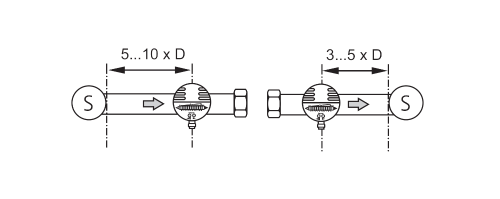
The SI sensor is the most reliable and repeatable when the sensor is installed in laminar flow. Valves, bends, flow constrictions, etc. all cause turbulence.
To avoid influences of turbulence, maintain a straight run of 5...10 x pipe diameter upstream of the sensor and 3...5 x pipe diameter after the sensor.

D = pipe diameter, S = source of turbulence