- Real-time maintenance
- Vibration
- Technology
- Frequency domain
Frequency domain
Every rotating machine has its own vibration signature made up of the combined individual parts. The amplitude of that signature changes when the machine experiences unusual operation, such as unbalance or bearing wear.
- Vibration in the time domain is the overall vibration of the machine. It’s what you feel when you put your hand on the machine and it is the combination of each component.
- Vibration in the frequency domain isolates each of the individual components. This allows you to pinpoint sources of defects before the machine catastrophically fails.
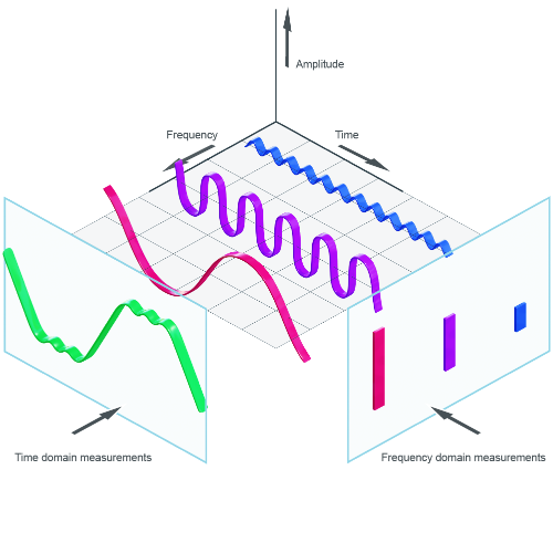
The cube below is often used to illustrate the time and frequency domains. The time domain measurements monitor the signal amplitude over time and the frequency domain monitors the signal amplitude by individual frequency.
Fast Fourier Transformation (FFT)
When there are vibration signals from multiple sources, as in the time domain, FFT analysis is used to separate the signals into the frequency domain. It is used for narrow band analysis such as unbalance.
Consider an example of a fan with 6 blades rotating at 60 rpm.

Unbalance on one blade increases vibration in the time domain and shows a spike at 1 Hz in the frequency domain (60 rpm = 1 rev / sec = 1 Hz)

Debris that hits every blade shows a spike at 6 Hz (1 Hz times 6 blades per rev)

When both faults are present, the time domain signal is mixed, but the frequency domain signal shows the same spikes at 1 Hz and 6 Hz.
FFT analysis is used to break up the overall vibration signal into its individual frequencies. The math is quite complex, but computer programs are available to perform the math. The image below shows the relationship between combined overall vibration signal, individual components' time domain signals, and individual components' frequency domain signals achieved through FFT analysis.

High frequency-FFT (H-FFT) analysis
H-FFT analysis is a special FFT analysis used for transient signals, such as faulty bearings or discrete tooth errors. The H-FFT is an FFT with some upstream filters and mathematical operations to separate the transient signal (i.e. bearing) from machine noise and other vibration sources like unbalance.
For example, the image below shows a typical time domain signal from a machine with unbalance and bearing damage with interfering signals from machine noise. The noise signature overpowers the vibration signals from the components.

Step 1: H-FFT analysis filters machine noise and vibration from components other than bearings.

Step 2: Positive and negative signals are rectified to all positive signals.

Step 3: Low-pass filter removes unimportant vibration leaving only vibration due to the rolling element bearing.

Step 4: Standard FFT analysis is then applied to separate the vibration into the individual signals for outer race, inner race and rolling element components.