- Valve sensors
- Target pucks and mounting sets for manual valves
Target pucks and mounting sets for manual valves
Reliable position monitoring of valve flaps and ball valves requires precisely matched accessories. Only by using the right combination of sensors and mechanical components can operating states be reliably monitored, downtime reduced and maximum plant availability ensured.
Position monitoring for automated quarter-turn actuators
In the case of quarter-turn actuators fitted with dual inductive sensors, an additional target puck is used. This ensures precise detection of the end positions and enables repeatable signal feedback to control or monitoring systems.
End position feedback for manual valves and ball valves
For manual shut-off valves, such as manually operated flaps or ball valves, a suitable mounting set is required. This ensures that both the sensor and the target puck are securely fastened in accordance with the relevant standards. As a result, reliable position feedback can be achieved at all times, even in manual applications.
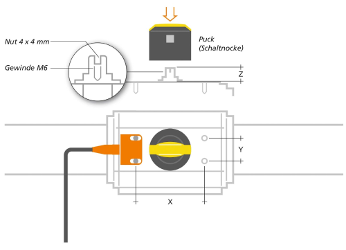
Target pucks play a key role in position monitoring of quarter-turn actuators. They are installed directly onto the drive shaft and must comply with the requirements of VDI/VDE 3845 to ensure a standard-compliant, compatible installation.
The metal targets integrated onto the target puck serve as defined actuating elements for the dual inductive sensor. Depending on the version, these targets are fixed at a 90° offset or freely adjustable, so that both standard applications and system-specific adaptations can be implemented without difficulty. This ensures precise damping of the sensor – and thus accurate feedback of the ‘Open’ and ‘Closed’ end positions.
The figure below shows the dimensions relevant for selecting the appropriate target puck according to VDI/VDE 3845. By comparing these dimensions with the specifications in the data sheet of the respective quarter-turn actuator, the appropriate target puck can be determined quickly and reliably using the corresponding selection table.
| Mounting dimensions X / Y [mm] | Height of the drive shaft Z [mm] | Diameter of the drive shaft [mm] |
Diameter [mm] | Description | Order no. |
|---|---|---|---|---|---|
| 80 / 30 | 30 | 38 | 53 | Target puck Basic | E12517 |
| 80 / 30 | 30 | < 38 | 53 | Target puck Adjustable | E12516 |
| 80 / 30 | 20 | < 38 | 53 | Target puck Basic + adapter | E12517 + E12526 (ZZ0566) |
| 80 / 30 | 20 | < 38 | 53 | Target puck Adjustable + adapter | E12516 + E12526 |
| 80 / 30 | 20 | < 38 | 53 | Target puck Basic | E12828 |
| 80 / 30 | 20 | < 38 | 53 | Target puck Basic 3-way | E12829 |
| 80 / 30 | 30 | < 53 | 65 | Target puck Multicover Basic | E12724 |
| 80 / 30 | 30 | < 53 | 65 | Target puck Multicover Adjustable | E12725 |
| 130 / 30 | 30 | < 90 | 102 | Large target puck Basic | E17328 |
| 130 / 30 | 30 | < 90 | 102 | Large target puck Adjustable | E17119 |
The systems are designed for use with dual inductive sensors (IND, INE) and continuous position sensors from the MVQ series, enabling precise and repeatable detection of the valve position. The 80 × 30 mm actuator interface according to VDI/VDE 3845 supports a wide range of compatible sensors and target pucks. At the same time, the mounting sets are designed for operating temperatures from –30 to +80 °C, making them ideally suited for demanding industrial environments.
The mounting sets feature a universal interface and are fully compatible with ISO flange valves according to DIN EN ISO 5211 in top flange sizes F03 to F16. A secure connection to the valve shaft is achieved via a robust shaft extension. The height-adjustable design allows for optimal adaptation to different valve geometries. The upper part, made of high-quality Vestamid plastic, allows for use in hazardous areas (only for articles compatible with the IND series), whilst the lower part and mechanical components are made of stainless steel. This ensures high corrosion resistance, a long service life and reliable operation even in harsh industrial environments.
The selection of the appropriate mounting set depends primarily on the diameter of the top flange. The shaft extension included in the mounting sets ensures a secure connection between the valve and the mounting set; it is selected based on the respective shaft diameter. By comparing the dimensions shown in the figure and table below with the specifications in the data sheet of the shut-off valve or ball valve, the appropriate mounting set can be clearly identified.

| Shaft extension | ||||||||||||
|---|---|---|---|---|---|---|---|---|---|---|---|---|
| Sensor type IND / INE | Sensor type MVQ | |||||||||||
| Top flange size according to ISO 5211 |
Pitch circle A [mm] |
Bore B [mm] |
Shaft diameter C [mm] |
M4 | M5 | M6 | M8 | M10 | M4 | M5 | M6 | M8 |
| F03 | 36 | 5 | 9 | E12588 | E12766 | |||||||
| F04 | 42 | 5 | 11 | E12519 | E12767 | |||||||
| F05 | 50 | 6 | 14 | E12589 | E12520 | E12521 | E12768 | E12769 | ||||
| F07 | 70 | 8 | 17 | E12522 | E12523 | E12770 | E12771 | |||||
| F10 | 102 | 10 | 22 | E12524 | ||||||||
| F12 | 125 | 12 | 27 | E12590 | ||||||||
| F14 | 140 | 16 | 36 | E12591 | ||||||||
| F16 | 165 | 20 | 46 | E12592 | ||||||||