- 3D object recognition
- Pallet Detection System (PDS)
- Integration of the PDS
Integration of the PDS
The key to a successful implementation of any solution is a firm understanding of all requirements. PDS is no different. This section provides all details required to ensure successful implementation of PDS. This includes:
- Mounting position:
Where and how the camera should be mounted to the vehicle. - Wiring:
How to wire the PDS solution (power supply/communication). - Software interface:
How the PDS solution is connected to the vehicle controller. - Detectable pallet types:
What types of pallets can be detected with the standard PDS solution.
Following these steps will ensure a successful PDS implementation.
The PDS solution
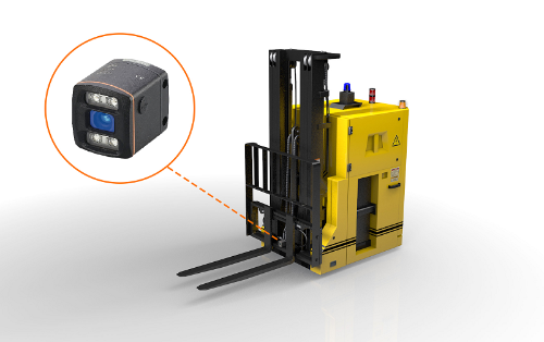
Mounting position:
Inclination
Mounting height

Wiring
The PDS is integrated in the O3D Camera. This camera requires a 24V DC power supply and communicates via Ethernet. The wiring of both interfaces is shown in the following image:
Connector: 1 x M12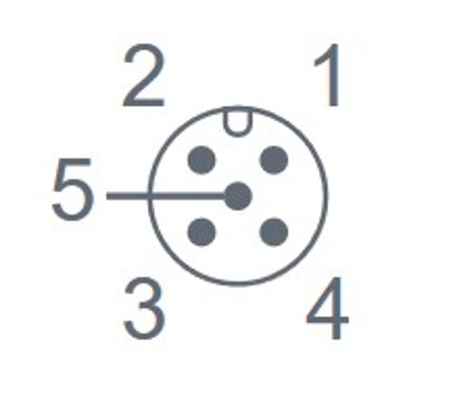 Electrical connection: Process connection |
Connector: 1 x M12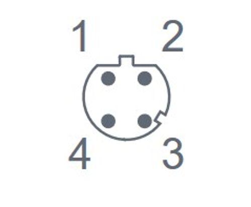 Electrical connection: Ethernet |
|---|---|
| 1. U+ | 1. TD+ |
| 2. Trigger input | 2. RD+ |
| 3. GND | 3. TD- |
| 4. Switching output 1 ready | 4. RD- |
| 5. Switching output 1 cascading |
Note: The camera requires 2.4 A peak current during image capture.
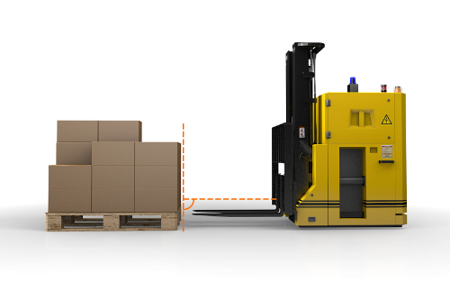
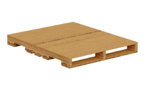
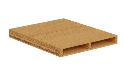
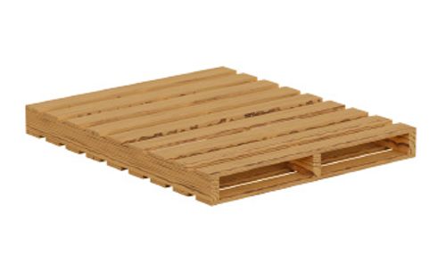
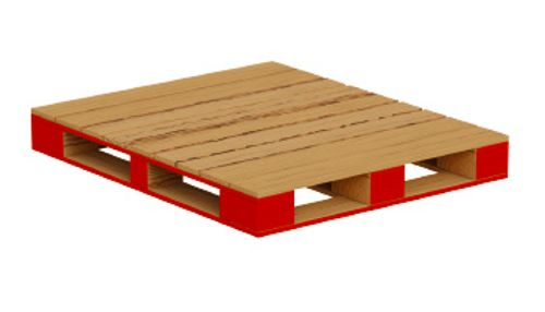
Detectable pallet types
The PDS is designed to detect pallets with two pallet pockets. A distinction is made between "block" and "stringer" pallets.
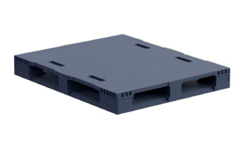
The PDS can be used to detect the following 2-pocket pallet geometries/types:
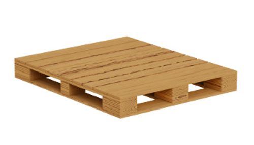 Wood, block |
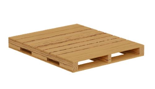 Wood, stringer |
 Plywood, stringer |
 Double-sided |
 Reversible |
 2-way |
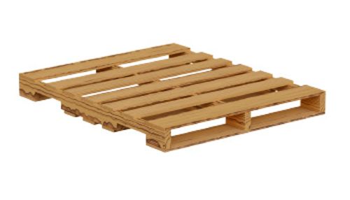 GMA 4-way |
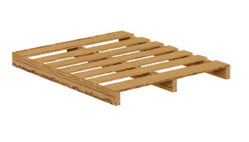 Single-face, stringer |
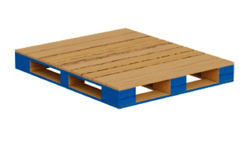 CHEP |
 PECO |
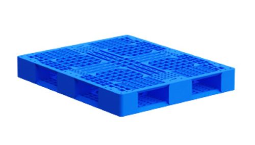 Plastic |
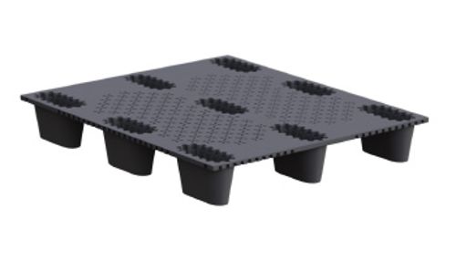 Nestable, plastic |
 IGPS |