Service Center 800-441-8246
  1. Products
  2. Sensors
  3. Flow sensors / flow meters
  4. All flow sensors / flow meters
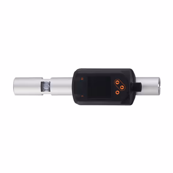
  5. SDP110

Gap distance sensor

SDP110

SDR14DGXFRKG/US-100

Gap distance sensor

SDP110

SDR14DGXFRKG/US-100

  • Air gap provided as absolute value
  • Precise values at all times due to pressure-compensated measuring principle
  • Enables zero gap and clogging detection
  • Self-cleaning measuring channel resists purge air pressure
  • Easy teaching of thresholds with just one click
  • Convenient operation via buttons or parameter setting via IO-Link
Learn more
  • ce
  • ukca
  • iolink
  • cul
Product characteristics
Number of inputs and outputs Number of digital outputs: 2; Number of analog outputs: 1
Process connection threaded connection G 1/4 DN8
Absolute
Measuring range
0...400; (depending on the nozzle used) µm
Relative (without unit of measurement)
Measuring range
0...800
Application
Application for industrial applications
Media compressed air
Medium temperature [°C] -10...60
Min. bursting pressure
64 bar 6.4 MPa
Pressure rating
16 bar 1.6 MPa
Electrical data
Operating voltage [V] 18...30 DC; (to SELV/PELV)
Current consumption [mA] < 80
Protection class III
Reverse polarity protection yes
Power-on delay time [s] 1
Inputs / outputs
Number of inputs and outputs Number of digital outputs: 2; Number of analog outputs: 1
Inputs
Inputs teach input
Outputs
Output signal switching signal; analog signal; IO-Link; (configurable)
Electrical design PNP/NPN
Number of digital outputs 2
Output function normally open / closed; (configurable)
Max. voltage drop switching output DC [V] 2.5
Permanent current rating of switching output DC [mA] 150; (per output)
Number of analog outputs 1
Analog current output [mA] 4...20; (scalable)
Max. load [Ω] 500
Short-circuit protection yes
Type of short-circuit protection yes (non-latching)
Overload protection yes
Measuring/setting range
Absolute
Measuring range
0...400; (depending on the nozzle used) µm
Setting range
0...500; (depending on the nozzle used) µm
Resolution
1 µm
Set point SP
2...500 µm
Reset point rP
0...498 µm
Analog start point ASP
0...400 µm
Analog end point AEP
100...500 µm
In steps of
1 µm
Relative (without unit of measurement)
Measuring range
0...800
Setting range
0...1000
Resolution
1
Set point SP
4...1000
Reset point rP
0...996
Analog start point ASP
0...800
Analog end point AEP
200...1000
In steps of
1
Pressure monitoring
Measuring range [bar] -1...16
Display range [bar] -1...20
Resolution [bar] 0.05
Set point SP [bar] -0.92...16
Reset point rP [bar] -1...15.92
Analog start point [bar] -1...12.8
Analog end point [bar] 2.2...16
In steps of [bar] 0.01
Flow monitoring
Measuring range
0.8...100 l/min 0.3...33.2 m/s 0.05...6 m³/h
Display range
0...120 l/min 0...39.8 m/s 0...7.2 m³/h
Resolution
0.2 l/min 0.1 m/s 0.01 m³/h
Set point SP
1.4...100 l/min 0.5...33.2 m/s 0.08...6 m³/h
Reset point rP
0.9...99.5 l/min 0.3...33 m/s 0.05...5.97 m³/h
Analog start point ASP
0...80 l/min 0...26.6 m/s 0...4.8 m³/h
Analog end point AEP
20...100 l/min 6.6...33.2 m/s 1.2...6 m³/h
Low flow cut-off LFC
0.6...1 l/min 0.2...0.3 m/s 0.04...0.06 m³/h
In steps of
0.1 l/min 0.1 m/s 0.01 m³/h
Accuracy / deviations
Accuracy (in the measuring range) ± (5% MW + 5 µm); (pressure 1...3 bar)
Repeatability ± (3% MW + 2 µm); (pressure 1...6 bar)
Pressure monitoring
Repeatability [% of the final value] ± 0,2
Characteristics deviation [% of the final value] < ± 0,5; (BFSL = Best Fit Straight Line)
Greatest TEMPCO of the span [% MEW / 10 K] ± 0,3
Greatest TEMPCO of the zero point [% MEW / 10 K] ± 0,1
Flow monitoring
Temperature coefficient [1/K] ± 0,07 % MW
Accuracy (in the measuring range) class 141: ± (2 % MW + 1 % MEW); class 344: ± (6 % MW + 1,2 % MEW) ; air quality to ISO 8573-1:2010; at medium temperature 23 °C
Repeatability ± (0,8 % MW + 0,4 % MEW)
Reaction times
Pressure monitoring
Response time [s] 0.05
Flow monitoring
Response time [s] 0.1; (dAP = 0)
Damping process value dAP [s] 0...5
Software / programming
Parameter setting options hysteresis / window; normally open / closed; current output; display can be rotated and switched off; Display unit; Teach function
Interfaces
Communication interface IO-Link
Transmission type COM2 (38,4 kBaud)
IO-Link revision 1.1
SDCI standard IEC 61131-9
SIO mode yes
Required master port class A
Process data analog 7
Process data binary 2
Min. process cycle time [ms] 7.2
Supported DeviceIDs
Type of operation DeviceID
default 1333
Note
For further information please see the IODD PDF file at "Downloads"
Operating conditions
Ambient temperature [°C] 0...60
Storage temperature [°C] -20...85
Max. relative air humidity [%] 90
Protection IP 65; IP 67
Tests / approvals
EMC
DIN EN 60947-5-9
Vibration resistance
DIN EN 68000-2-6 5 g (10...2000 Hz)
MTTF [years] 167
UL approval
UL approval number I012
File number UL E174189
Pressure equipment directive sound engineering practice; can be used for stable gases fluid group 2
Mechanical data
Weight [g] 548.2
Material PBT+PC-GF30; PPS GF40; stainless steel (1.4301 / 304); stainless steel (1.4305 / 303); steel (1.5523) galvanized; 2.0401 (brass / CW614N); FKM
Materials (wetted parts) EN AW-6082 (aluminium); stainless steel (1.4305 / 303); FKM; ceramics glass passivated; PPS GF40; Al2O3 (ceramics); acrylate; SINT-A51; stainless steel (1.4301 / 304); CW510L (brass)
Process connection threaded connection G 1/4 DN8
Displays / operating elements
Display
Color display 1,44", 128 x 128 pixels
2 x LED, yellow
Remarks
Remarks
MW = Measured value
MEW = Final value of the measuring range
Measuring, display and setting ranges refer to standard volume flow according to DIN ISO 2533.
For information about installation and operation please see the operating instructions.
Pack quantity 1 pcs.
Electrical connection
Connection Connector: 1 x M12; coding: A