Search
US
Products
Markets
IIoT & Solutions
Company
Resources
Supply Chain Software
my ifm
Products
Sensors
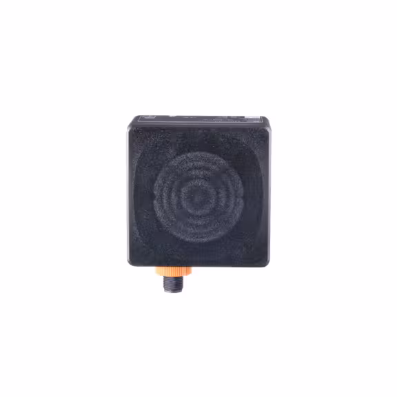
Radar sensors
Radar distance sensors
R1D102