- Encoders
- Technology
Encoder technology
Magnetic technology
Magnetic encoders use Hall-effect sensors to detect rotary movements. The sensors detect the orientation of a permanent magnet attached to the shaft. A microprocessor then calculates the angle of rotation of the shaft from the sensor signals. Due to its simple mechanical principle, a magnetic encoder is smaller and much more robust than an optical encoder.
Also in terms of measuring performance, the new generation of magnetic-based encoders can now keep up with optical encoders: Thanks to powerful microprocessors, optimised signal processing software and an implemented temperature compensation, the measuring precision is increased to better than 0.1 degrees. Deviations due to thermal conditions are reduced to a minimum. In addition, the encoder’s response time, which previously ranged between 700 and 1,400 microseconds, has been reduced to levels approaching zero microseconds, offering the response behaviour of an optical encoder.
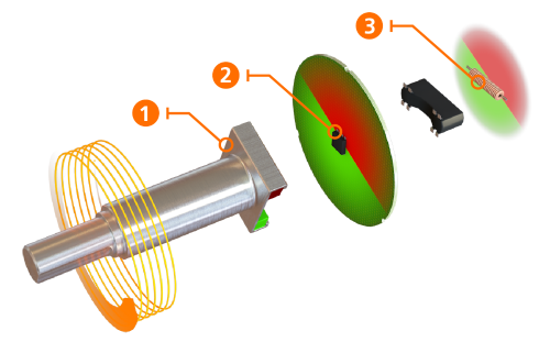
No value is lost: the Wiegand effect
Magnetic encoders detect rotations at angles between 0 and 360 degrees, but the Hall-effect sensor cannot detect the number of full revolutions without an external power supply. This is where the integrated energy harvesting system comes in, which is based on the Wiegand effect and supplies the revolution counter circuit with short, powerful voltage pulses. This means that the encoder can also reliably detect and store low-speed revolutions without any external power supply. This rules out wrong allocations of the position due to shaft rotation outside of machine running times, for example due to pressure loss in a lifting mechanism.
Optical technology
Through-beam sensors emit light through the slots which are etched onto a coated glass disc. Pulses are generated as the beams are broken.
- Optical encoders are very precise.
- Optical encoders are very complex units consisting of many individual components.
- The production of coated glass discs is difficult and expensive. As compared to encoders with magnetic technology, they easily break when they are exposed to shock and vibration.
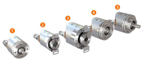
Flange and shaft types at a glance
- RB / RMB type as synchro flange with 6mm shaft
- RA / RMA type as direct flange with hollow shaft
- RO / RMO type as direct flange with hollow shaft
- RU / RMU type as synchro flange with 6mm solid shaft
- RV / RMV as clamp flange and10mm solid shaft
Shaft designs
Solid shaft
Encoders with solid shaft are attached to rotating machine shafts with the same or a similar diameter using a coupling. These couplings compensate for mechanical offsets between the two shafts, thus preventing premature wear. This makes this combination well suited for applications subjected to regular shock or vibration.
Hollow shaft
Hollow shaft encoders are installed directly on the rotating shafts. Shaft couplings are not required, which facilitates assembly. Instead, they use a flexible mounting flange, called a stator coupling, which compensates slight installation misalignments. Encoders with hollow shaft open to one side do not have a through mounting hole.
Shaft diameter and construction size
The correct shaft diameter is important to ensure that the incoming shaft is held precisely in place.
Common diameters for solid shafts are 6mm, 8mm and 10mm.
Common diameters for hollow shafts open to one side are between 6 and 15mm. For high flexibility of diameters, adapter sleeves of 6 to 14mm are inserted into the hollow shaft.
The outer diameter of an encoder is generally expressed as the construction size. ifm encoders are available in sizes 36 to 58 mm.