You probably do not come from: United Arab Emirates. If necessary, change to: United States

Monitoring of the cooling circuit for the fermentation tanks at the distillery

Food industry
Beverages Cold chain
Industry 4.0
IIoT platform moneo
Monitoring and maintenance
Real-time maintenance
Use Case

Steinhauser distillery

Knowing how much energy is used in the production of spirits and wines

In the production process of wines and spirits, the fermentation process is essential. During this process, the temperature must be monitored at all times to ensure optimum taste and quality of the products. If the fermentation process is to be slowed down or stopped, for example, the product is cooled down in the tank. Even a small deviation in the fermentation time can result in a considerable loss of flavour.

The important task of temperature regulation is performed in the Steinhauser distillery & winery by means of two large refrigeration units. Their cooling line network is connected to every tank in production. The coolant in the flow and return lines is monitored by means of sensors.

The starting position

The Steinhauser company has continued to expand in recent years, so that the required capacity of the cooling unit was no longer ensured. Furthermore, it was not possible to collect data regarding the energy costs for the production of a product.

Goal of the project

Energy measurement in the production process of spirits

The aim is to ensure that the required amount of coolant is quickly available at the respective tank. In addition, the connection to moneo is to make it possible for the first time to monitor and document the actual cooling energy used. This will allow conclusions to be drawn about the actual amounts of energy consumed for product manufacture.

Implementation

Two new refrigeration units were installed in the outdoor area of the Steinhauser company. Then lines were laid to each individual fermentation tank. Flow and temperature sensors were installed in the flow and return lines of each cooling water line. The process data is transmitted via IO-Link masters to the moneo system installed on a moneo|appliance. By means of moneo RTM, all process values in the flow and return lines of the respective production lines are recorded and displayed.

Using the moneo function “Calculated values”, dataflow models were created to calculate the current cooling capacity. Besides, the current system values of the cooling units are transmitted to moneo. From the recorded values, the costs for energy and electricity consumption as well as transport and power losses can be calculated.

Success

Effective, efficient use of energy

Two major advantages result from the expansion of the monitoring of the cooling circuit, as the temperature of the tank contents is permanently monitored and the fermentation process can be controlled very precisely.

  • The CO2 consumption per tank can be measured from the process values provided.
  • The cooling process can be implemented efficiently and according to demand.

Layout

  1. Temperature sensor in the flow line – old wine cellar line 1 – TA2417
  2. Magnetic-inductive flow meter in the return line – old wine cellar line 1 – SM9000
  3. Temperature sensor in the flow line – old wine cellar line 2 – TA2417
  4. Magnetic-inductive flow meter in the return line – old wine cellar line 2 – SM9000
  5. Temperature sensor in the flow line – liquor cellar line 1 – TV7405
  6. Magnetic-inductive flow meter in the return line – liquor cellar line 1 – SM8020
  7. Temperature sensor in the flow line – liquor cellar line 2 – TV7405
  8. Magnetic-inductive flow meter in the return line – liquor cellar line 2 – SM8020
  9. Temperature sensor in the flow line – new wine cellar line 1 – TA2417
  10. Magnetic-inductive flow meter in the return line – new wine cellar line 1 – SM2000
  11. Refrigeration unit

Our customer

The Steinhauser distillery in Kressbronn on Lake Constance has existed since 1828 and is still family-owned today. 
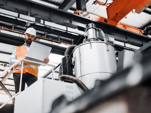
In 1996, Steinhauser renewed itself and now operates the most modern bonded distillery in Europe. ifm sensors and the moneo software have been used there since 2021 – with success, the distillery’s products are award-winning.

Learn more in the video report ➜

System structure

  1. Flow meter in the return line - SM2000 / SM9000 (new and old wine cellar)
  2. Flow meter in the return line – SM8020 (liquor cellar)
  3. Temperature sensor in the flow line – TA2417 / TV7405 (new and old wine cellar and liquor cellar)
  4. Refrigeration unit with Modbus interface
  5. IO-Link master – AL1353
  6. LR Agent (installed on a server)
  7. moneo RTM as an appliance QHA210

Dashboard

This dashboard provides the user with an overview of all relevant process values for the entire refrigeration system

Dashboard Overview
  1. Input power of the refrigeration unit** (kW)
  2. Total energy consumption of the refrigeration unit to date** (kW/h)
  3. Outside temperature of the refrigeration unit** (°C)
  4. Coolant temperature at the evaporator outlet of the refrigeration unit** (°C)
  5. Coolant temperature at the evaporator inlet of the refrigeration unit** (°C)
  6. Cooling capacity – old wine cellar line 1 CDS* (kW)
  7. Cooling capacity – old wine cellar line 2 CDS* (kW)
  8. Cooling capacity – liquor cellar line 1 CDS* (kW)
  9. Cooling capacity – new wine cellar line 1 CDS* (kW)
  10. Cooling capacity – liquor cellar line 2 CDS* (kW)

* CDS (Calculated Data Source) stands for a value calculated via the moneo Dataflow Modeler
** Values are read via the Modbus interface of the refrigeration unit
 

This dashboard provides the user with an overview of all relevant process values of the refrigeration unit

Dashboard
  1. Input power of the refrigeration unit (kW)
  2. Total energy consumption of the refrigeration unit to date (kW/h)
  3. Operating hours counter of the refrigeration unit (h)
  4. Outside temperature of the refrigeration unit (°C)
  5. Coolant temperature at the evaporator outlet of the refrigeration unit (°C)
  6. Coolant temperature at the evaporator inlet of the refrigeration unit (°C)

The following dashboard provides the user with all current process values of the refrigeration circuit in the liquor cellar

Dashboard
  1. Coolant temperature in the flow line – liquor cellar line 1 – TV7405 (°C)
  2. Coolant temperature in the return line – liquor cellar line 1 – SM8020 (°C)
  3. Coolant flow in the return line – liquor cellar line 1 – SM8020 (l/min)
  4. Coolant temperature in the flow line – liquor cellar line 2 – TV7405 (°C)
  5. Coolant temperature in the return line – liquor cellar line 2 – SM8020 (°C)
  6. Coolant flow in the return line – liquor cellar line 2 – SM8020 (l/min)
  7. Cooling capacity – liquor cellar line 1 CDS* (kW)
  8. Cooling capacity – liquor cellar line 2 CDS* (kW)

The dashboard “New wine cellar – line 1” provides the user with a detailed view of the respective coolant line of the refrigeration system

Dashboard
  1. Coolant temperature in the flow line – TA2417 (°C)
  2. Coolant temperature in the return line – SM2000 (°C)
  3. Coolant flow in the return line – SM2000 (l/min)
  4. Coolant totaliser in the return line – SM2000 (l)
  5. Cooling capacity – new wine cellar line 1 CDS* (kW)

Detailed view: SM2000 flow meter in the return line – new wine cellar line 1

Dashboard SM2000
  1. Coolant flow value - SM2000 (l/min)
  2. Coolant temperature value – SM2000 (°C)
  3. Coolant totaliser – SM2000 (l)
  4. Line chart of the coolant flow rate – SM2000 (l/min)

Analysis

The analysis function can be used to view further details. The screenshot shows the ratio between the temperature value in the flow line and the temperature value and flow value in the return line of the cooling circuit on line 1 in the new wine cellar

Analysis
  1. Coolant flow value - SM2000 (l/min)
  2. Coolant temperature value in the flow line – TA2417 (°C)
  3. Coolant temperature value in the return line – SM2000 (°C)

Calculated values

Using moneo, much more information can be calculated from the process values of the sensors.

The “Dataflow Modeler” enables custom creation of calculated values, e.g. by combining and offsetting data sources from sensors in a dataflow model.

Calculation of the cooling capacity of line 1 in the new wine cellar

Dataflowmodel
  1. Temperature value of the SM2000 flow meter in the return line (°C)
  2. Temperature value of the TA2417 temperature sensor in the flow line (°C)
  3. Function block “Subtraction” for calculating the temperature difference
  4. Flow value of the SM2000 flow meter in the return line (l/min)
  5. Constant “60” for converting litres per minute to litres per hour
  6. Function block “Multiplication” for converting litres per minute to litres per hour
  7. Constant “0.000446”: thermal conductivity of the coolant used (kW/m*k)
  8. Function block “Multiplication” for calculating the heat capacity per hour
  9. Function block “Multiplication” for calculating the cooling capacity (kW)
  10. Result: cooling capacity of line 1 in the new wine cellar (kW)