- PI sanitary pressure transmitter
- Technology
Principle of operation for flush pressure transmitters
Ceramic measure cell provides robust sensing technology with long-term stability
The most important element of the ceramic capacitive technology is the ceramic (Al2O3) measuring cell. After assembly, the ceramic cell element resembles a plate capacitor with a reference electrode and a measuring electrode placed 0.01 mm apart. The capacitance is inversely proportional to the distance between the electrodes. As pressure is applied, the distance changes by a small value and the capacitance changes proportionately. This analog signal is then converted into a digital pressure by the sensor’s microprocessor.
Note the signal change as pressure is applied to the sensor in the animation below.
Cell construction
The strength of the ceramic capacitive measuring cell comes from the overall design of the process connection and measuring cell. The ceramic itself it very hard, and the ceramic diaphragm is supported by the ceramic base in case of overpressure. The complete measuring cell is also centered and supported by a brass locating ring behind the body of the ceramic cell. The measuring cell is placed in the bottom of the process connection and then the locating ring is threaded into place creating a very robust support system. This is how we can achieve very high-pressure ratings. Alternatively, a stainless steel diaphragm is supported by the fill fluid, but this is not a rigid or robust system.
Main advantages of the ceramic capacitive measuring cell
- Robust direct sensing measurement technology
- Eliminates possibility of contamination from diaphragm fill fluid
- Long-term stability of ceramic cell design does not fatigue like stainless steel
- Internal support construction creates very high pressure ratings
- Ceramic cell is more resistant to abrasion, dents or dings that can create measurement offsets
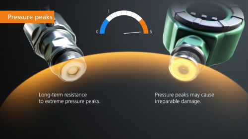
- Highest overload pressure rating, especially with dynamic pressure peaks
Technology comparison: ceramic vs stainless steel diaphragm

- Pressure ratings can be comparable on paper, but diaphragms must be handled with care and any imperfection in the diaphragm will result in a weak point.

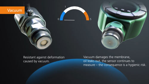
- The same applies in vacuum applications, and the fill fluid can also heat up and expand resulting in deformation of the diaphragm.

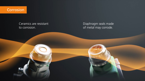
- The wetted parts consist of 99.9% ceramic, 316L stainless steel and PTFE, all of which have high chemical resistance. The stainless steel on the ceramic cell is much thicker and only a portion of the surface area, making it more resistant to corrosion than a thin steel diaphragm

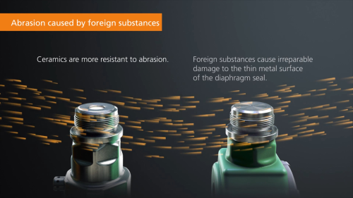
- Ceramic is harder and more abrasion resistant than a thin stainless steel diaphragm
Summary of technology comparison
- Metal diaphragms are fragile and must be handled with care. The diaphragm profile can easily be damaged during shipping or normal handling resulting in a permanent offset.
- Diaphragms rely on fill fluid to transfer energy to the measuring cell, and when the diaphragm is damaged or worn, the fill fluid can leak into the process. Even though most fill fluids are FDA approved, this can reduce product quality or result in scrapped product. A leaking diaphragm sensor can often seem to operate normally for some period of time as the process media replaces the fill fluid and acts on the measuring cell directly. The fill fluid then enters the process unknowingly.
- One advantage of the fluid filled diaphragm is its thermal insulation properties that greatly reduce the impact of temperature shocks and isolate changes in media temperature from the sensor electronics. For this reason, ifm offers fluid filled diaphragm units, series PI22 / PI23 with 200 ºC (392 ºF) continuous media temperature rating.
- One challenge of the ceramic cell is that it does require sealing between the measuring cell and process connection. ifm has optimized this design mechanically and we use a very stable PTFE seal, which is hygienic and compatible with most media found in Food & Beverage applications. We also have all the common sanitary approvals certifying and accepting this design.
Relative pressure measurement and atmospheric vent
All relative pressure, often referred to as gauge pressure, measurements require a reference to atmospheric pressure or the surrounding ambient environment. The pressure measurement is a differential between atmospheric and system pressure, therefore “relative” to atmospheric pressure. To accomplish this most pressure sensors use some sort of vent system, which opens the measuring cell to atmosphere, so the system pressure is measured above or below (vacuum) this reference.
ifm has optimized the location and design of the atmospheric vent to improve machine availability and process performance.
Optimized atmospheric vent location
The vent is located 90° from the display to optimize vent orientation while keeping the display in a preferred position
Optimizing the vent orientation (keeping the membrane vertical) allows the Gore-Tex membrane to shed moisture, which prevents clogging and reduces measurement errors due to incorrect reference pressure.
Proven vent design
ifm rigorously tested design variations to improve cleanability, breathability, and flow of media though the vent.
Everything from the amount and size of holes to improve flow through the vent to the drip edge which prevents media from entering the vent were considered. This prevents build-up in the vent which can cause measurement offsets and increases machine performance.