- moneo: IIoT platform
- Use cases
Volumetric flow monitoring of a CIP plant using moneo RTM
Cleaning process control in the food and beverage industry
When processing biological substances destined for consumption, such as milk, strict hygiene is vital.One of the decisive factors for a perfect cleaning result is the flow and thus the mechanical effect.
![]()
The initial situation:
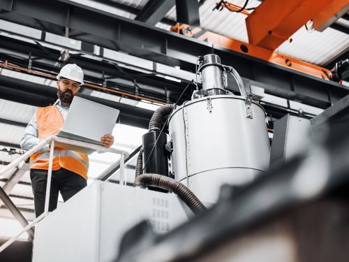
ifm performs tests with process sensors in a real environment using their own CIP plant. Before moneo was introduced, the plant was operated via analogue signals and controlled via a PLC. Visualisation of the process was only possible on site at the plant's HMI. Surveillance was restricted to the analogue 4...20mA signal value.
![]()
Aim of the project:
By connecting existing analogue flow sensors to the moneo system via an IO-Link master, another process analysis step is added. This improves the quality of the process and creates transparency in the overall process.
![]()
Implementation:
moneo is already installed centrally on a server and the necessary modules, including moneo RTM, are activated. The IO-Link masters are connected to the server via an internal VLAN.
An already installed analogue sensor from Endress & Hauser (Promag 50) was used to record the flow. It was made IO-Link capable by retrofitting (ifm Y path). An evaluation system and display for analogue signals (DP2200) was used. This has an analogue input 4...20mA. The signal can additionally be looped through the unit and is thus still available for the plant’s PLC. This enables easy integration without affecting the plant control.
![]()
The result:
- Data recording has increased transparency, resulting in optimisation potentials.
- The higher plant uptime has improved the overall process.
- Integrated alarm management ensures fast reaction to changing process parameters, optimising maintenance.
- All measures increase process and product quality.
- moneo RTM ensures detailed process visualisation.
![]()
Bottom line:
The plant was digitised successfully without any changes or interventions to the existing PLC or software.

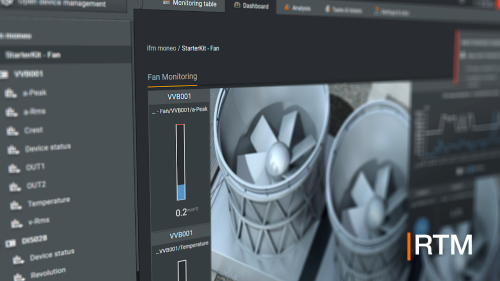
Dashboard
The moneo dashboard provides the user with an overview of the relevant process values for this plant. The following dashboard visualises the primary parameters (flow, temperature and conductivity) in the inlet:

- Pressure at the feed pump in bar
- Conductivity in the inlet in µS/cm
- Flow in L/min
- Flow velocity in m/s
- Temperature in the inlet before the heat exchanger in °C
- Temperature in the inlet after the heat exchanger in °C
Another dashboard shows more details about the flow.

- Current pressure at the feed pump in bar
- Comparison of pump pressure and flow in a line diagram
- Raw value of the DP2200 input signal in mA
- Calculated flow rate from the analogue current value in L/min
- Calculated flow velocity from the flow rate in m/s
Analysis
Via the analysis function, the user can analyse the tank level in detail. The level values are permanently recorded and can even be checked after days, weeks or months. In this way, conclusions can be drawn about leakages, for example.

- Pressure at the feed pump in bar
- Flow in L/min
Calculated values:
The following values are calculated additionally based on the volumetric flow.
Current flow in L/min
The start and stop values of the analogue sensor were determined using the data sheet:
- Start value 4mA = 0 L/min
- Stop value 20mA = 200 L/min
This results in a valency per milliamp of 12.5 L/min.
This 12.5 L/min per milliamp is now used as a factor for calculation.

- Present current value in mA
- Factor 12.5 l/min per mA
- Offset -4 for conversion from 4...20mA to 0...16mA
- Multiplication factor with current value
- Result of the calculation in L/min
Conversion flow (L/min) to velocity (m/s)
The flow velocity is a decisive parameter for the success of the cleaning process; this value can be determined on the basis of the current flow and the constant cross-sectional area of the pipe.
V = velocity in metres per second [m/s]
Q = flow in cubic metres per second [m³/s]
A = cross-sectional area in square metres [m²]
Example with pipe radius 0.02m and a flow of 200L/min:

- Current flow in L/min
- Factor for converting L/min into m³/s (1 minute = 60 seconds, 1,000 litres = 1m³)
- Constant radius of the pipeline in m
- Constant Pi (3.1415)
- Flow in L/min divided by 60,000 gives flow in m³/s
- Squaring the radius (r²)
- Multiplication r² by Pi, result cross-sectional area in square metres
- Flow in m³/s divided by cross-sectional area (m²)
- Result of the calculation in m/s