Condition-based monitoring of fans
Plan maintenance times perfectly and ensure good air quality
Goal of the project
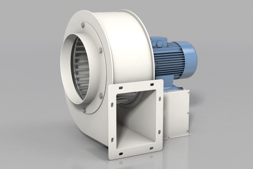
Inconspicuous, often hidden, and yet so important: the effective functioning of extraction systems and, therefore, fans in factory buildings is hugely important. For example, carefully removing soldering fumes and fine dust during laser marking is essential. Otherwise, the consequences could be quality deterioration, health risks, or even a complete production stoppage. Fans are therefore an integral part of many production processes.
To ensure that they fully fulfil their function, they are usually serviced or replaced at fixed intervals. However, this does not take into account the actual soiling of the fan. Moreover, “maintenance according to schedule” results in high (but avoidable!) costs, as components that are still functional are replaced and machines are brought to a standstill for maintenance without it actually being necessary.
The solution therefore lies in continuous status checks: by constantly monitoring the fan using a condition monitoring tool, sustainable maintenance can be planned. Expensive and unnecessary production stoppages and failures can be avoided and machine availability increased.
Maintaining decent air quality is also essential for protecting the health of employees in manufacturing.
Avoidance of unplanned |
Early detection |
Setup possible |
|
On average, customers achieve: |
||
|
6.5 h savings in labour hours |
4.5 h savings by preventing |
€ 5,000 cost savings through prevention |
How fan monitoring and maintenance are connected
To ensure that your fans enjoy all-round protection, ifm moneo offers complete solutions for holistic maintenance. Malfunctions are detected in good time and unplanned downtime is avoided. A rapid response to changes in the process parameters is possible thanks to an integrated alarm management system. Necessary maintenance can be scheduled to minimise plant downtime. Software-supported maintenance documentation makes it easy to identify recurring wear and contamination and take appropriate action.
The entire production process is monitored, ensuring consistent process and quality assurance. This increases plant availability, optimises the production process and saves resources. The solutions from ifm – a well-thought-out and continuously developed combination of sensors and software – are suitable for different types of fans.
Value proposition
|
|
How does condition-based fan monitoring work?
The IIoT software solution moneo enables efficient and reliable fan monitoring. The sensor values are recorded directly at the fan and provide detailed information about the condition of the component. Detailed visualisation of all sensors in the process is carried out using individual cockpit functions in moneo.
Thanks to the early detection of imminent damage in moneo, failure of the extraction system can be prevented. As a result, potentially serious consequences for personnel and machines can be avoided.
moneo simulation video
Turn data into information: From fans to material planning
Automated fan maintenance planning not only offers numerous advantages , but also enables direct forwarding of warnings and alarms. The maintenance engineer receives an email message directly from moneo if values move outside the specified ranges.
The data collected via the sensors and processed in moneo can also be put to further use: The smart IIoT data is exported to your respective ERP system in real time via an interface (ifm SAP add-on). This shop floor integration (SFI) interface enables optimisation of business and production processes. In this specific case, condition monitoring has an influence on material and maintenance planning in SAP, for example.
ifm also offers the necessary interfaces to store your data in the cloud and use it for further analysis if necessary.
Would you have imagined that by monitoring a fan you can also optimise production throughput?

- moneo
MQTT or OPC UA → AWS, Azure, SAP - SAP Integration
SFI (shop floor integration) → SAP PM - Alarm
email notification (threshold) - Spare parts
automatic ordering through SAP - Cloud and on-premises
possible with the cloud and on-premises solutions
How to use moneo without any programming skills
Constant monitoring of fans is crucial for condition-based maintenance and thereby a trouble-free production process. By choosing ifm, you are choosing hardware and software from a single source – and therefore a consistent solution from the sensor to the moneo IIoT platform. For this purpose, the moneo IIoT software, which also includes a condition monitoring tool, is installed on the target system. The sensors (vibration, temperature and speed) are mounted and connected electrically. With the free-of-charge moneo configure you can quickly and easily put your fan monitoring into operation and directly create the parameter set required for your production process.
All the sensors in the process are then visualised informatively in moneo. When threshold deviations occur, moneo displays a warning or an alarm. Depending on the customer’s wishes, an email can be sent to the responsible specialist in the company or to the SAP PM module. In the event of a warning, orders for spare parts can also be sent out automatically.
Benefit from the condition monitoring of your fan, detect even small changes in good time and optimise your production and maintenance processes.

System structure
- IO-Link master (VLAN)
- IO-Link vibration sensor
- IO-Link temperature sensor
- IO-Link speed sensor
- moneo configure free
moneo software
- Analysis and model calculation
- Historical data
- Visualisation
- Monitoring
- Alarm function
- On-premises or cloud