You probably do not come from: Lithuania. If necessary, change to: United States
  1. Products
  2. Sensors
  3. Level sensors
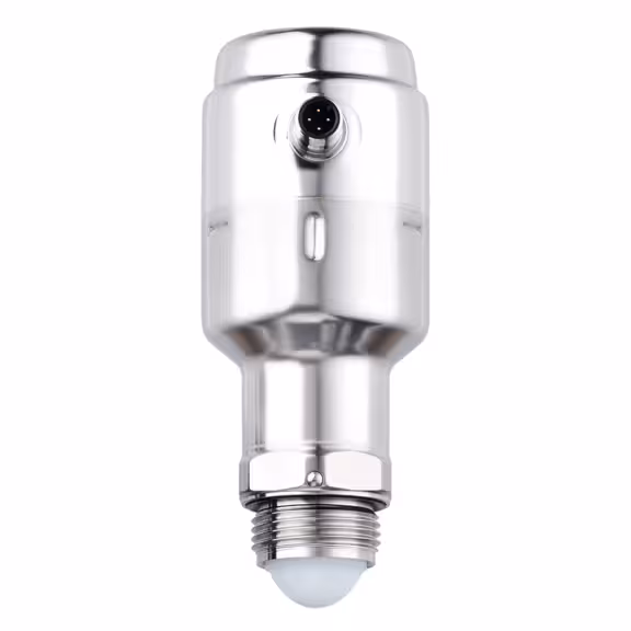
  4. Non-contact level measurement for hygienic applications
  5. LW2720

continuous level sensor

LW2720

NON-CONTACT LEVEL TRANSMITTER

continuous level sensor

LW2720

NON-CONTACT LEVEL TRANSMITTER

  • 80 GHz frequency enables level measurement with millimetre precision of up to 10 metres
  • Non-contact measuring principle: no malfunctions due to deposits or wear
  • Certified for use in hygienic areas
  • Simple installation and maintenance-free operation
  • Remote sensor parameter setting and level monitoring via connection to the IT system
  • Intuitive set-up and visualisation of the measured data using the ifm Vision Assistant software
An IO-Link master and a parameter setting software (e.g. moneo or LR DEVICE) are required for initial set-up.
  • ce
  • fda
  • ukca
  • ehedg
  • fcc
  • iolink
  • cul
  • ec19352004
  • 3a
  • crn
Product characteristics
Number of inputs and outputs Number of digital outputs: 1; Number of analogue outputs: 1
Process connection G 1 Aseptoflex Vario
Application
Special feature Gold-plated contacts
Dielectric constant of the medium ≥ 2
Recommended media water; hydrous media
Medium temperature [°C] -40...150; (see diagram:)
Maximum speed of the change of level [mm/s] 200
Pressure rating [bar] 8
Note on pressure rating
0 bar at medium temperature < - 20 C
Vacuum resistance [mbar] -1000
MAWP (for applications according to CRN) [bar] 8
Radio approval for EU/RED; United Kingdom; South Korea; USA; Canada; Australia; New Zealand; Vietnam; Singapore
Note on radio approval
The list of countries applying the European Radio Equipment Directive 2014/53/EU (RED) can be found under “Downloads”.
Electrical data
Operating voltage [V] 18...30 DC
Current consumption [mA] < 80
Protection class III
Reverse polarity protection yes
Power-on delay time [s] < 15
Measuring principle FMCW (80 GHz technology); frequency range 77 - 81 Hz
Inputs / outputs
Number of inputs and outputs Number of digital outputs: 1; Number of analogue outputs: 1
Outputs
Total number of outputs 2
Output signal switching signal; analogue signal; IO-Link
Electrical design PNP/NPN
Number of digital outputs 1; (2 parameterisable)
Output function normally open / normally closed; (parameterisable)
Max. voltage drop switching output DC [V] 2.5
Permanent current rating of switching output DC [mA] 50
Number of analogue outputs 1
Analogue current output [mA] 4...20, invertible; (scalable)
Max. load [Ω] 43,5 * (Ub – 18) + 600 Ω
Short-circuit protection yes
Type of short-circuit protection pulsed
Overload protection yes
Measuring/setting range
Measuring range [m] 10; (see diagram:)
Sampling rate [Hz] > 3
Accuracy / deviations
Accuracy
± 2 mm
Resolution [mm] 1
Zero signal (current) [mA] 3.8
Full signal (current) [mA] 20.5
Temperature drift per 10 K ± 1 mm
Response times
Response time [ms] 330
Interfaces
Communication interface IO-Link
Transmission type COM2 (38,4 kBaud)
IO-Link revision 1.1
SDCI standard IEC 61131-9
Profiles Smart Sensor ED2: SSCs (0x8001), Measuring Sensor (0x000A)
SIO mode yes
Required master port type A
Process data analogue 1
Process data binary 2
Min. process cycle time [ms] 6
Supported DeviceIDs
Type of operation DeviceID
default 1324
Operating conditions
Ambient temperature [°C] -40...80
Note on ambient temperature
see diagram:
Storage temperature [°C] -40...90
Protection IP 68; IP 69K
Tests / approvals
EMC
DIN EN 61326-1 group 1: Class A (IO-Link active); B (IO-Link not active, with analogue and switching outputs)
Shock resistance
DIN EN 60068-2-27 50 g (11 ms) / 20 g (6 ms)
Vibration resistance
IEC 61298-3 2 g (10...1000 Hz)
MTTF [years] 330
Mechanical data
Weight [g] 727.15
Materials stainless steel (1.4404 / 316L); PA; FKM; FVMQ
Materials (wetted parts) PTFE; EPDM
Process connection G 1 Aseptoflex Vario
Surface characteristics Ra/Rz of the wetted parts < 0.76
Remarks
Notes An IO-Link master and a parameter setting software (e.g. moneo or LR DEVICE) are required for initial set-up.
Pack quantity 1 pcs.
Electrical connection
Connection Connector: 1 x M12; coding: A; Contacts: gold-plated
Diagrams and graphs
Angle of radiation
Angle of radiation (α): 10°
distance (D) 2 m - Beam width (W) 0.4 m
distance (D) 4 m - Beam width (W) 0.7 m
distance (D) 6 m - Beam width (W) 1.1 m
distance (D) 8 m - Beam width (W) 1.4 m
distance (D) 10 m - Beam width (W) 1.8 m
X process temperature °C
Y Ambient temperature °C
1 Adapter example E33208
A accuracy
B distance